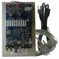
CRD44600-PH-FB Cirrus Logic Inc, CRD44600-PH-FB Datasheet - Page 10

CRD44600-PH-FB
Manufacturer Part Number
CRD44600-PH-FB
Description
Ref Bd For 6ch CS44600 W/ PH Pwr Stg
Manufacturer
Cirrus Logic Inc
Datasheet
1.CRD44600-PH-FB.pdf
(32 pages)
Specifications of CRD44600-PH-FB
Amplifier Type
Class D
Output Type
2-Channel (Stereo)
Max Output Power X Channels @ Load
100W x 2 @ 8 Ohm
Voltage - Supply
35 V ~ 50 V
Operating Temperature
-10°C ~ 70°C
Board Type
Fully Populated
Utilized Ic / Part
CS44600
Lead Free Status / RoHS Status
Contains lead / RoHS non-compliant
Other names
598-1023
4. ELECTROMAGNETIC INTERFERENCE (EMI)
10
4.1
4.2
This reference design from Cirrus Logic is a board level solution which is meant to control
emissions by minimizing and suppressing them at the source in contrast to containing them
in an enclosure. Utilizing spread spectrum modulation techniques to reduce the overall
switching energy, along with a low internal modulator clock frequency of 24.576 MHz, the ra-
diated emissions are greatly reduced. These features allow for the use of very low cost com-
ponents to couple the high frequency noise to chassis ground. No common mode chokes,
inductors, or power line filters were required.
power supplies. Audio amplifiers are usually located in close proximity to radio receivers, par-
ticularly AM receivers which are notoriously sensitive to interference. Amplifiers also need to
operate with speaker leads of unpredictable length and construction which make it possible
for any high frequency currents that appear on the outputs to generate nuisance emissions.
The EMI requirements for an amplifier have added dimensions beyond those imposed on
Several techniques are used in the circuit design and board layout to minimize high fre-
quency fields in the immediate vicinity of the high power components. Specific techniques
include the following:
•
•
•
•
It is extremely critical that the layout of the power amplifier section of the Cirrus Logic
CS44600 Reference Design be copied as exactly as possible to assure best RF/EMI per-
formance.
The CRD44600-PH-FB has been tested to CISPR and FCC Class B limits for radiated and
power line conducted emissions. The same test setup and test signal were used for all
tests. The setup consisted of an unregulated linear power supply, CRD44600-PH-FB
board, 5m of speaker cable, and two 8-Ω resistive loads. This setup is shown in Figure 4
Suppression of EMI at the Source
As was mentioned in Section 3.2, effective power supply decoupling of high frequency cur-
rents, and minimizing the loop area of the decoupling loop is one aspect of minimizing EMI.
Each output of the TDA8939 includes “snubbing” components. For example, OUT1 of U1 in-
cludes snubber components R18/R30 (5.6 Ω) and C34/C46 (560 pF). These components serve
to damp ringing on the switching outputs in the 30-50 MHz range. The snubbing components
should be as close as practical to the output pins to maximize their effectiveness. Again, refer
to Figure 15 for the preferred component layout.
A separate ground plane with a capacitively coupled electrical connection to the chassis and
which surrounds the speaker output connector should be implemented. This allows the speaker
outputs to be AC coupled to the chassis just before they exit the chassis from the speaker con-
nector. Again, refer to Figure 15 for the preferred component layout.
Make use of source termination resistors on all digital signals whose traces are longer than ap-
proximately 25 mm.
EMI Testing
CRD44600-PH-FB
MAR '05 DS633RD1


