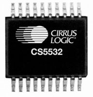
CS5532-BSZR Cirrus Logic Inc, CS5532-BSZR Datasheet - Page 3

CS5532-BSZR
Manufacturer Part Number
CS5532-BSZR
Description
IC,Data Acquisition Signal Conditioner,2-CHANNEL,24-BIT,CMOS,SSOP,20PIN,PLASTIC
Manufacturer
Cirrus Logic Inc
Datasheet
1.CS5532-BSZ.pdf
(50 pages)
Specifications of CS5532-BSZR
Number Of Bits
24
Sampling Rate (per Second)
3.84k
Data Interface
Serial
Number Of Converters
1
Power Dissipation (max)
45mW
Voltage Supply Source
Analog and Digital, Dual ±
Operating Temperature
-40°C ~ 85°C
Mounting Type
Surface Mount
Package / Case
20-SSOP
Lead Free Status / RoHS Status
Lead free / RoHS Compliant
For Use With
598-1159 - BOARD EVAL FOR CS5532U ADC
Lead Free Status / RoHS Status
Lead free / RoHS Compliant
Available stocks
Company
Part Number
Manufacturer
Quantity
Price
LIST OF FIGURES
LIST OF TABLES
DS755F3
Figure 1. SDI Write Timing (Not to Scale)............................................................................... 11
Figure 2. SDO Read Timing (Not to Scale)............................................................................. 11
Figure 3. Multiplexer Configuration ......................................................................................... 12
Figure 4. Input models for AIN+ and AIN- pins ....................................................................... 13
Figure 5. Measured Voltage Noise Density............................................................................. 13
Figure 6. CS5532/34 Register Diagram .................................................................................. 14
Figure 7. Command and Data Word Timing ........................................................................... 22
Figure 8. Guard Signal Shielding Scheme .............................................................................. 24
Figure 9. Input Reference Model when VRS = 1 .................................................................... 25
Figure 10. Input Reference Model when VRS = 0 .................................................................. 25
Figure 11. Self Calibration of Offset ........................................................................................ 32
Figure 12. Self Calibration of Gain .......................................................................................... 32
Figure 13. System Calibration of Offset .................................................................................. 32
Figure 14. System Calibration of Gain .................................................................................... 32
Figure 15. Synchronizing Multiple ADCs................................................................................. 36
Figure 16. Digital Filter Response (WR = 60 Sps) .................................................................. 38
Figure 18. 120 Sps Filter Phase Plot to 120 Hz ...................................................................... 38
Figure 17. 120 Sps Filter Magnitude Plot to 120 Hz ............................................................... 38
Figure 19. Z-Transforms of Digital Filters................................................................................ 38
Figure 20. On-chip Oscillator Model........................................................................................ 39
Figure 21. CS5532 Configured with a Single +5 V Supply ..................................................... 40
Figure 22. CS5532 Configured with ±2.5 V Analog Supplies.................................................. 41
Figure 23. CS5532 Configured with ±3 V Analog Supplies..................................................... 41
Figure 24. CS5532 Configured for Thermocouple Measurement ........................................... 42
Figure 25. Bridge with Series Resistors .................................................................................. 42
Table 1. Conversion Timing – Single Mode ............................................................................ 34
Table 2. Conversion Timing – Continuous Mode .................................................................... 35
Table 3. Command Byte Pointer ............................................................................................. 35
Table 4. Output Coding for 24-bit CS5532 and CS5534......................................................... 37
CS5532/34-BS
3


