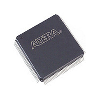
EPM1270GT144I5N Altera, EPM1270GT144I5N Datasheet - Page 40

EPM1270GT144I5N
Manufacturer Part Number
EPM1270GT144I5N
Description
MAX II
Manufacturer
Altera
Datasheet
1.EPM1270GT144I5N.pdf
(88 pages)
Specifications of EPM1270GT144I5N
Family Name
MAX II
Memory Type
Flash
# Macrocells
980
Frequency (max)
1.8797GHz
Propagation Delay Time
10ns
Number Of Logic Blocks/elements
127
# I/os (max)
116
Operating Supply Voltage (typ)
1.8V
In System Programmable
Yes
Operating Supply Voltage (min)
1.71V
Operating Supply Voltage (max)
1.89V
Operating Temp Range
-40C to 100C
Operating Temperature Classification
Industrial
Mounting
Surface Mount
Pin Count
144
Package Type
TQFP
Lead Free Status / Rohs Status
Compliant
Available stocks
Company
Part Number
Manufacturer
Quantity
Price
Company:
Part Number:
EPM1270GT144I5N
Manufacturer:
ALTERA
Quantity:
612
2–32
Table 2–7. MAX II MultiVolt I/O Support
Referenced Documents
MAX II Device Handbook
Notes to
(1) To drive inputs higher than V
(2) When V
(3) When V
(4) When V
(5) MAX II devices can be 5.0-V tolerant with the use of an external resistor and the internal I/O clamp diode on the EPM1270 and EPM2210
(6) When V
(7) When V
VCCIO (V)
1.5
1.8
2.5
3.3
device, enable the I/O clamp diode to prevent V
devices.
drain setting with internal I/O clamp diode (available only on EPM1270 and EPM2210 devices) and external resistor is required.
Table
CC IO
CC IO
CC IO
CC IO
CC IO
f
2–7:
= 1.8 V, a MAX II device can drive a 1.5-V device with 1.8-V tolerant inputs.
= 3.3 V, a MAX II device can drive a device with 5.0-V TTL inputs but not 5.0-V CMOS inputs. In the case of 5.0-V CMOS, open-
= 2.5 V, a MAX II device can drive a 1.5-V or 1.8-V device with 2.5-V tolerant inputs.
= 3.3 V and a 2.5-V input signal feeds an input pin, the VCCIO supply current will be slightly larger than expected.
= 3.3 V, a MAX II device can drive a 1.5-V, 1.8-V, or 2.5-V device with 3.3-V tolerant inputs.
1.5 V
v
v
—
—
Connect VCCIO pins to either a 1.5-V, 1.8 V, 2.5-V, or 3.3-V power supply, depending
on the output requirements. The output levels are compatible with systems of the
same voltage as the power supply (that is, when VCCIO pins are connected to a 1.5-V
power supply, the output levels are compatible with 1.5-V systems). When VCCIO
pins are connected to a 3.3-V power supply, the output high is 3.3 V and is compatible
with 3.3-V or 5.0-V systems.
For information about output pin source and sink current guidelines, refer to the
428: MAX II CPLD Design
This chapter referenced the following documents:
■
■
■
■
1.8 V
AN 428: MAX II CPLD Design Guidelines
DC and Switching Characteristics
Hot Socketing and Power-On Reset in MAX II Devices
Handbook
Using User Flash Memory in MAX II Devices
v
v
—
—
C CIO
but less than 4.0 V including the overshoot, disable the I/O clamp diode. However, to drive 5.0-V inputs to the
Input Signal
v
2.5 V
v
v
v
(4)
(Note 1)
I
from rising above 4.0 V.
3.3 V
v
v
v
v
Guidelines.
Table 2–7
v
5.0 V
—
—
—
(5)
chapter in the MAX II Device Handbook
summarizes MAX II MultiVolt I/O support.
v
v
v
1.5 V
v
(2)
(3)
(6)
chapter in the MAX II Device Handbook
v
v
1.8 V
v
—
(3)
(6)
chapter in the MAX II Device
Output Signal
v
© October 2008 Altera Corporation
2.5 V
v
—
—
(6)
Chapter 2: MAX II Architecture
Referenced Documents
3.3 V
v
—
—
—
v
5.0 V
—
—
—
(7)
AN


