RDK-251 Power Integrations, RDK-251 Datasheet - Page 3
RDK-251
Manufacturer Part Number
RDK-251
Description
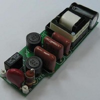
KIT REF DESIGN FOR LNK457D
Manufacturer
Power Integrations
Series
LinkSwitch®-PLr
Datasheet
1.RDK-251.pdf
(60 pages)
Specifications of RDK-251
Current - Output / Channel
350mA
Outputs And Type
1, Isolated
Voltage - Output
12 ~ 18 V
Features
Dimmable
Voltage - Input
90 ~ 265VAC
Utilized Ic / Part
LNK457D
Output Voltage
12 V
Input / Supply Voltage (max)
265 VAC
Input / Supply Voltage (min)
90 VAC
Duty Cycle (max)
39.9 %
Mounting Style
Through Hole
Output Current
350 mA
Output Power
5 W
Lead Free Status / RoHS Status
Lead free / RoHS Compliant
Other names
596-1345
Available stocks
Company
Part Number
Manufacturer
Quantity
Price
Company:

Part Number:
RDK-251
Manufacturer:
Power Integrations
Quantity:
135


Table of Contents
1
2
3
4
5
6
7
8
9
10
11
Page 3 of 60
4.1
4.2
4.3
4.4
4.5
4.6
4.7
8.1
8.2
8.3
8.4
8.5
8.6
9.1
9.2
9.3
9.4
9.5
9.6
9.7
10.1
10.2
10.3
10.4
11.1
11.2
Introduction .................................................................................................................5
Power Supply Specification ........................................................................................7
Schematic ...................................................................................................................8
Circuit Description.......................................................................................................9
PCB Layout...............................................................................................................12
Bill of Materials .........................................................................................................13
Transformer Design Spreadsheet .............................................................................14
Transformer Specification .........................................................................................17
Performance Data.....................................................................................................23
9.7.1
9.7.2
11.1.1
11.1.2
11.1.3
11.1.4
11.1.5
Thermal Performance............................................................................................35
Waveforms ............................................................................................................38
Dimming Performance Circuit Design Considerations .........................................9
Input EMI Filtering and Input Rectification .........................................................10
Active Damper ...................................................................................................10
Bleeder ..............................................................................................................10
LinkSwitch-PL Primary.......................................................................................11
Output Rectification ...........................................................................................11
Output Feedback ...............................................................................................11
Electrical Diagram..............................................................................................17
Electrical Specifications .....................................................................................17
Materials ............................................................................................................17
Transformer Build Diagram................................................................................18
Transformer Construction ..................................................................................19
Winding Illustrations...........................................................................................20
Active Mode Efficiency.......................................................................................23
Non-Dimmable Configuration ............................................................................24
Dimmable ..........................................................................................................24
Harmonics .........................................................................................................25
Power Factor .....................................................................................................27
Line Regulation..................................................................................................28
Dimming Performance .......................................................................................29
Thermal Set-up ..................................................................................................35
Equipment Used ................................................................................................36
Thermal Result ..................................................................................................36
Thermal Scan ....................................................................................................37
Drain Voltage and Current .................................................................................38
Output Current Start-up Profile ..........................................................................44
Dimming Range..........................................................................................29
Unit to Unit Tracking ...................................................................................33
Normal Steady State Operation..................................................................38
AC Start-up.................................................................................................40
115 V TRIAC in Series with AC Input .........................................................40
230 V TRIAC in Series with AC Input .........................................................42
Fault Conditions (Output Shorted / Open Circuit) .......................................43
Tel: +1 408 414 9200 Fax: +1 408 414 9201
Power Integrations
www.powerint.com
Related parts for RDK-251
Image
Part Number
Description
Manufacturer
Datasheet
Request
R

Part Number:
Description:
KIT REF DESIGN TOP HX FOR TOP258
Manufacturer:
Power Integrations
Datasheet:

Part Number:
Description:
KIT REF DESIGN LINKSWITCH 2
Manufacturer:
Power Integrations
Datasheet:

Part Number:
Description:
KIT REF DESIGN 1.2W PS TN FAMILY
Manufacturer:
Power Integrations
Datasheet:

Part Number:
Description:
KIT REF DESIGN 36-72W MOTOR DRVR
Manufacturer:
Power Integrations
Datasheet:

Part Number:
Description:
REFERENCE DESIGN LINKSWITCH-PH
Manufacturer:
Power Integrations
Datasheet:

Part Number:
Description:
Specifications: Manufacturer: Power Integrations ; Output Voltage: 380 VDC ; Input / Supply Voltage (Max): 264 VAC ; Input / Supply Voltage (Min): 90 VAC ; Mounting Style: Through Hole ; Output Current: 0.913 A ; Output Power: 347 W
Manufacturer:
Power Integrations, Inc.

Part Number:
Description:
Power Management Modules & Development Tools TOPSwitch-JX REF. DESIGN KIT
Manufacturer:
Power Integrations
Datasheet:
Part Number:
Description:
Power Management IC Development Tools REF DESIGN RDR-292 PFF LED STREET LIGHT
Manufacturer:
Power Integrations

Part Number:
Description:
KIT REF DESIGN FOR LNK403EG
Manufacturer:
Power Integrations
Datasheet:

Part Number:
Description:
KIT REF DESIGN FOR LNK406EG
Manufacturer:
Power Integrations
Datasheet:
Part Number:
Description:
KIT REF DESIGN 36-72W MOTOR DRVR
Manufacturer:
Power Integrations
Datasheet:
Part Number:
Description:
REFERENCE DESIGN LINKSWITCH-PH
Manufacturer:
Power Integrations
Datasheet:
Part Number:
Description:
Specifications: Manufacturer: Power Integrations ; Output Voltage: 380 VDC ; Input / Supply Voltage (Max): 264 VAC ; Input / Supply Voltage (Min): 90 VAC ; Mounting Style: Through Hole ; Output Current: 0.913 A ; Output Power: 347 W
Manufacturer:
Power Integrations, Inc.
Part Number:
Description:
Specifications: Family: Eval Boards - DC/DC & AC/DC (Off-Line) SMPS ; Series: HiperLCS™ ; Main Purpose: DC/DC, Step Down ; Outputs and Type: 1, Isolated ; Power - Output: 150W ; Voltage - Output: 24V ; Current - Output: 6.25A ; Voltage - Input:
Manufacturer:
Power Integrations, Inc.
Datasheet: