KAC-9618 Eastman Kodak Company, KAC-9618 Datasheet - Page 5
KAC-9618
Manufacturer Part Number
KAC-9618
Description
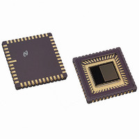
IC SENSOR IMAGE VGA MONO 48-CLCC
Manufacturer
Eastman Kodak Company
Type
CMOS Imagingr
Datasheet
1.KAC-9618.pdf
(43 pages)
Specifications of KAC-9618
Pixel Size
7.5µm x 7.5µm
Active Pixel Array
648H x 488V
Frames Per Second
30
Voltage - Supply
3.3V
Package / Case
48-CLCC
Lead Free Status / RoHS Status
Lead free / RoHS Compliant
Other names
LM9618IEA
LM9618IEA
LM9618IEA
Available stocks
Company
Part Number
Manufacturer
Quantity
Price
Company:

Part Number:
KAC-9618
Manufacturer:
IXYS
Quantity:
2 100


IMAGE SENSOR SOLUTIONS
Pin Descriptions
www.kodak.com/go/imagers 585-722-4385
Pin
1
2
3
4
5
6
7
8
9
10
11
12
13
14
15
16
17
18
19
20
21
22
23
Name
vsrvdd
vrl
vdd_pix
RSVD
sadr
sda
sclk
snapshot
resetb
pdwn
vss_dig
vdd_dig
hsync
vsync
pclk
mclk
d0
RSVD
oe
d1
d2
d3
d4
I/O
0
I
I
I
IO
I
I
I
I
I
I
IO
IO
IO
I
O
I
O
O
O
O
Typ
P
A
P
D
D
D
D
D
D
P
P
D
D
D
D
D
D
D
D
D
D
Description
Charge pump output, connect to ground via a1.0µf capacitor.
Anti blooming pin. This pin is normally tied to ground.
3.3 volt supply for the pixel array.
This pin is reserved for future use, do not connect.
Digital input with pull down resistor. This pin is used to program different slave addresses
for the sensor in an I
I
driver.
I
Digital input with pull down resistor used to activate (trigger) a snapshot sequence.
Digital input with pull up resistor. When forced to a logic 0 the sensor is reset to its default
power up state. The resetb signal is internally synchronized to mclk which must be run-
ning for a reset to occur.
Digital input with pull down resistor. When forced to a logic 1 the sensor is put into power
down mode.
0 volt power supply for the digital circuits.
3.3 volt power supply for the digital circuits.
Digital Bidirectional. This is a dual mode pin. When the sensor’s digital video port is con-
figured to be a master, (the default), this pin is an output and is the horizontal synchroni-
zation pulse. When the sensor’s digital video port is configured to be a slave, this pin is
an input and is the row trigger.
Digital Bidirectional. This is a dual mode pin. When the sensor’s digital video port is con-
figured to be a master, (the default), this pin is an output and is the vertical synchroniza-
tion pulse. When the sensor’s digital video port is configured to be a slave, this pin is an
input and is the frame trigger.
Digital output. The pixel clock.
Digital input. The sensor’s master clock input.
Digital output. Bit 0 of 11 of the digital video output bus. This output can be put into tri-
state mode.
This pin is reserved for future use, do not connect.
Digital input with pull down resistor. When forced to a logic 1 the sensor’s digital video
port d[11:0], vsync & hsync will be tri-stated.
Digital output. Bit 1 of 11 of the digital video output bus. This output can be put into tri-
state mode.
Digital output. Bit 2 of 11 of the digital video output bus. This output can be put into tri-
state mode.
Digital output. Bit 3 of 11 of the digital video output bus. This output can be put into tri-
state mode.
Digital output. Bit 4 of 11 of the digital video output bus. This output can be put into tri-
state mode.
2
2
C compatible serial interface data bus. The output stage of this pin has an open drain
C compatible serial interface clock.
2
C compatible system.
5
Email:imagers@kodak.com
Related parts for KAC-9618
Image
Part Number
Description
Manufacturer
Datasheet
Request
R

Part Number:
Description:
IC PROCESSOR IMAGE DGTL REALTIME
Manufacturer:
Eastman Kodak Company

Part Number:
Description:
HEADBOARD FOR KAC-9618
Manufacturer:
Eastman Kodak Company

Part Number:
Description:
HEADBOARD FOR KAC-9619
Manufacturer:
Eastman Kodak Company

Part Number:
Description:
HEADBOARD FOR KAC-9628
Manufacturer:
Eastman Kodak Company

Part Number:
Description:
HEADBOARD FOR KAC-9630
Manufacturer:
Eastman Kodak Company

Part Number:
Description:
HEADBOARD FOR KAC-9637
Manufacturer:
Eastman Kodak Company

Part Number:
Description:
HEADBOARD FOR KAC-9638
Manufacturer:
Eastman Kodak Company

Part Number:
Description:
HEADBOARD FOR KAC-9647
Manufacturer:
Eastman Kodak Company

Part Number:
Description:
HEADBOARD FOR KAC-9648
Manufacturer:
Eastman Kodak Company
Part Number:
Description:
HEADBOARD FOR KAC-9627
Manufacturer:
Eastman Kodak Company
Part Number:
Description:
KIT EVALUATION SENSOR KAC-9618
Manufacturer:
Eastman Kodak Company
Part Number:
Description:
KIT EVALUATION SENSOR KAC-9638
Manufacturer:
Eastman Kodak Company
Part Number:
Description:
KIT EVALUATION SENSOR KAC-9628
Manufacturer:
Eastman Kodak Company
Part Number:
Description:
KIT EVALUATION SENSOR KAC-9637
Manufacturer:
Eastman Kodak Company
Part Number:
Description:
KIT EVALUATION SENSOR KAC-9647
Manufacturer:
Eastman Kodak Company