ADNB-6001-EV Avago Technologies US Inc., ADNB-6001-EV Datasheet
ADNB-6001-EV
Specifications of ADNB-6001-EV


Related parts for ADNB-6001-EV


ADNB-6001-EV Summary of contents
Page 1
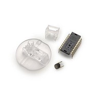
... The ADNS-6000 sensor along with the ADNS-6120 or ADNS-6130-001 lens, ADNS-6230-001 clip and ADNV- ADNB-6001-EV and ADNB-6002-EV laser mouse bundles include: Bundle Part Number Part Number ADNB-6001-EV ADNS-6000 ...
Page 2
... Overview of ADNB-6001-EV Laser Mouse Assembly Figure 1. Assembly drawing of ADNB-6001-EV (top, front and cross-sectional view) 2 ...
Page 3
... Assembly Drawing of ADNB-6001-EV, PCBs and Base Plate ADNS-6000 (sensor) Customer Supplied PCB ADNS-6120 (lens)* Customer Supplied Base Plate With Recommended Features Per IGES Drawing Figure 2. Exploded view drawing Shown with ADNS-6120 Laser Mouse Lens, ADNS-6230- 001 VCSEL Assembly Clip and ADNV-6340 VCSEL. The components interlock as they are mounted onto defined features on the base plate ...
Page 4
Assembly Recommendation 1. Insert the sensor and all other electrical components into the application PCB (main PCB board and VCSEL PCB board). 2. Wave solder the entire assembly in a no-wash solder process utilizing a solder fixture. The solder fixture ...
Page 5
Design considerations for improving ESD Performance For improved electrostatic discharge performance, typical creepage and clearance distance are shown in the table below. Assumption: base plate construction as per the Avago Technologies supplied IGES file for ADNS-6120 round lens. Typical Distance ...
Page 6
Notes (for figure 5) • Caps for pins 11, 12, 16 and 18 MUST have trace lengths LESS than each side. • Pins 16 and 18 caps MUST use pin 17 GND. • Pin 9, if used, ...
Page 7
Laser Output Power Parameter Symbol Laser output power LOP LASER Output Power The laser beam output power as measured at the navi- gation surface plane is specified below. The following conditions apply: 1. The system is adjusted according to the ...
Page 8
ADNS-6000 Laser Mouse Sensor Theory of Operation The ADNS-6000 is based on LaserStream Technol- ogy, which measures changes in position by optically acquiring sequential images (frames) and mathematically determining the direction and magnitude of movement. ADNS-6000 contains an Image Acquisition ...
Page 9
CAUTION advised that normal static precautions be taken in handling and assembly of this component to prevent damage and/or degradation which may be induced by ESD A Figure 8. Package outline drawing 9 A Notes. 1. Dimensions in ...
Page 10
External PROM The ADNS-6000 must operate from externally loaded programming. This architecture enables immediate adoption of new features and improved performance algorithms. The external program is supplied by Avago as a file, which may be burned into a programmable device. ...
Page 11
Absolute Maximum Ratings Parameter Symbol Storage Temperature T S Operating Temperature T A Lead Solder Temp Supply Voltage V DD3 ESD Input Voltage V IN Output current I OUT Input Current I IN Recommended Operating Conditions Parameter Symbol Operating Temperature ...
Page 12
AC Electrical Specifications Electrical Characteristics over recommended operating conditions. Typical values at 25 °C, V Parameter Symbol VDD to RESET t OP Data delay after RESET t PU-RESET T IN-RST Input delay after reset Power Down t PD Wake from ...
Page 13
DC Electrical Specifications Electrical Characteristics over recommended operating conditions. Typical values at 25 °C, V Parameter Symbol DC Supply Current I DD_AVG Power Down Supply I DDPD Current Input Low Voltage V IL Input High Voltage V IH Input hysteresis ...
Page 14
Typical Performance Characteristics Typical Resolution vs. Z 1000 900 800 700 600 500 400 300 200 Recommended Operating Region 100 0 1.5 1.6 1.7 1.8 1.9 2.0 2.1 2.2 2.3 2.4 2.5 2.6 2.7 2.8 2.9 3.0 3.1 3.2 3.3 ...
Page 15
Relative Responsivity for ADNS-6000 1 0.9 0.8 0.7 0.6 0.5 0.4 0.3 0.2 0.1 0 400 500 600 Figure 15. Relative Responsivity Synchronous Serial Port The synchronous serial port is used to set and read pa- rameters in the ADNS-6000, ...
Page 16
Write Operation Write operation, defined as data going from the micro- controller to the ADNS-6000, is always initiated by the micro-controller and consists of two bytes. The first byte contains the address (seven bits) and has a “1” as its ...
Page 17
Required timing between Read and Write Commands (tsxx) There are minimum timing requirements between read and write commands on the serial port. SCLK t HOLD-MISO t DLY-MISO MISO D 0 Figure 19. MISO Delay and Hold Time If the rising ...
Page 18
Motion Read Reading the Motion_Burst register activates this mode. The ADNS-6000 will respond with the contents of the Motion, Delta_X, Delta_Y, SQUAL, Shutter_Upper, Shutter_Lower, and Maximum_Pixel registers in that order. After sending the register address, the micro- controller must wait ...
Page 19
Frame Capture This is a fast way to download a full array of pixel values from a single frame. This mode disables navigation and overwrites any downloaded firmware. A hardware reset is required to restore navigation, and the firmware must ...
Page 20
The pixel output order as related to the surface is shown below. Top Xray View of Mouse Positive Y last output 899 898 897 896 895 894 893 892 891 890 889 888 887 886 885 884 883 882 881 ...
Page 21
Notes on Power-up and the serial port Reset Circuit The ADNS-6000 does not perform an internal power up self-reset; the reset pin must be raised and lowered to reset the chip. This should be done every time power is applied. ...
Page 22
Registers The ADNS-6000 registers are accessible via the serial port. The registers are used to read motion data and status as well as to set the device configuration. Address Register 0x00 Product_ID 0x01 Revision_ID 0x02 Motion 0x03 Delta_X 0x04 Delta_Y ...
Page 23
Product_ID Access: Read Bit 7 6 Field PID PID 7 6 Data Type: 8-Bit unsigned integer USAGE: This register contains a unique identification assigned to the ADNS-6000. The value in this register does not change; it can be used to ...
Page 24
Motion Access: Read Bit 7 6 Field MOT Reserved Data Type: Bit field. USAGE: Register 0x02 allows the user to determine if motion has occurred since the last time it was read. If so, then the user should read registers ...
Page 25
Delta_X Access: Read Bit 7 6 Field Data Type: Eight bit 2’s complement number. USAGE: X movement is counts since last report. Absolute value is determined by resolution. Reading clears the register. -128 -127 Motion Delta_X ...
Page 26
SQUAL Access: Read Bit 7 6 Field Data Type: Upper 8 bits of a 10-bit unsigned integer. USAGE: SQUAL (Surface Quality measure of ¼ of the number of valid features visible by the sensor ...
Page 27
Pixel_Sum Access: Read Bit 7 6 Field Data Type: High 8 bits of an unsigned 16-bit integer. USAGE: This register is used to find the average pixel value. It reports the upper byte of a 16-bit ...
Page 28
Configuration_bits Access: Read/Write Bit 7 6 LASER_ Field 0 MODE Data Type: Bit field USAGE: Register 0x0a allows the user to change the configuration of the sensor. Shown below are the bits, their default values, and optional values. Field Name ...
Page 29
Extended_Config Access: Read/Write Bit 7 6 Field Busy Reserved Data Type: Bit field USAGE: Register 0x0b allows the user to change the configuration of the sensor. Shown below are the bits, their default values, and optional values. Field Name Description ...
Page 30
Data_Out_Lower Access: Read Bit 7 6 Field Data_Out_Upper Access: Read Bit 7 6 Field Data Type: Sixteen bit word USAGE: Data in these registers come from the system self test or the ...
Page 31
Shutter_Lower Access: Read Bit 7 6 Field Shutter_Upper Access: Read Bit 7 6 Field Data Type: Sixteen bit unsigned integer. USAGE: Units are clock cycles. Read Shutter_Upper first, then Shutter_Lower. They should ...
Page 32
Mean Shutter vs. Z (White Paper) 800dpi, Circle@7.5" diameter, Speed-6ips 200 180 160 140 120 100 -0.8 -0.6 -0.4 -0.2 Distance from Lens Reference Plane to Surface, Z (mm) Figure 30. Mean Shutter vs. Z ...
Page 33
Frame_Period_Lower Access: Read Bit 7 6 Field Frame_Period_Upper Access: Read Bit 7 6 Field Data Type: Sixteen bit unsigned integer. USAGE: Read these registers to determine the current frame period and to ...
Page 34
Frame_Capture Access: Read/Write Bit 7 6 Field Data Type: Bit field. USAGE: Writing 0x83 to this register will cause the next available complete 1 2/3 frames of pixel values to be stored to SROM RAM. Writing ...
Page 35
Configuration II Access: Read/Write Bit 7 6 Field Reserved Reserved Data Type: Bit field USAGE: Write to this register Field Name Description BIT 2 Must be set to one 0 = LASER_NEN functions as normal Force_disable 1 = LASER_NEN output ...
Page 36
Frame_Period_Max_Bound_Lower Access: Read/Write Bit 7 6 Field FBM FBM 7 6 Frame_Period_Max_Bound_Upper Access: Read/Write Bit 7 6 Field FBM FBM 15 14 Data Type: 16-bit unsigned integer. USAGE: This value sets the maximum frame period (the MINIMUM frame rate) which ...
Page 37
Frame_Period_Min_Bound_Lower Access: Read/Write Default Value: 0x7E Bit 7 6 Field FBm FBm 7 6 Frame_Period_Min_Bound_Upper Access: Read/Write Default Value: 0x0E Bit 7 6 Field FBm FBm 15 14 Data Type: 16-bit unsigned integer. USAGE: This value sets the minimum frame ...
Page 38
Shutter_Max_Bound_Lower Access: Read/Write Bit 7 6 Field Shutter_Max_Bound_Upper Access: Read/Write Bit 7 6 Field Data Type: 16-bit unsigned integer. USAGE: This value sets the maximum allowable shutter value when operating in automatic ...
Page 39
LP_CFG0 Access: Read/Write Bit 7 6 Field Match LP 6 Data Type: 8-bit unsigned integer USAGE: This register is used to set the laser current and bin matching parameter used together with register 0x2D where register ...
Page 40
Reserved Address: 0x2f-0x3C Observation Access: Read/Write Bit 7 6 Field OB Reserved 7 Data Type: Bit field USAGE: Each bit is set by some process or action at regular intervals, or when the event occurs. The user must clear the ...
Page 41
Pixel_Burst Access: Read Bit 7 6 Field Data Type: Eight bit unsigned integer USAGE: The Pixel_Burst register is used for high-speed access to all the pixel values from one and 2/3 complete frame. See the Synchronous ...
Page 42
ADNV-6340 Single-Mode Vertical-Cavity Surface Emitting Laser (VC-SEL) Description This advanced class of VCSELs was engineered by Avago Technologies to provide a laser diode with a single longitudinal and a single transverse mode. In contrast to most oxide-based single-mode VCSELs, this ...
Page 43
Absolute Maximum Ratings: Parameter DC Forward current Peak Pulsing current [1] Power Dissipation Reverse voltage [2] Laser Junction Temperature Operating case Temperature Storage case Temperature Lead Soldering Temperature [3] ESD (Human-body model) Notes: 1. Duration = 100ms, 10% duty cycle ...
Page 44
Typical Characteristics Forward Voltage vs. Forward Currents 2.5 2.0 1.5 1.0 0.5 0 Forward Current (mA) Figure 33. Forward Voltage vs. Forward Current 4.5 4.0 3.5 3.0 2.5 2.0 1.5 1.0 0 Forward ...
Page 45
Figure 36. Recommended Reflow Soldering Profile 255 ˚C 250 ˚C 217 ˚ 150 sec 125 ˚C 40 ˚C ...
Page 46
ADNS-6120 and ADNS-6130-001 Laser Mouse Lens Description The ADNS-6120 and ADNS-6130-001 laser mouse lens are designed for use with Avago Technologies laser mouse sensors and the illumination subsystem provided by the ADNS-6230-001 VCSEL assembly clip and the ADNV- 6340 Single-Mode ...
Page 47
Max +0.2mm protrusion is allowed at the molding gate of either 1 side of lens. Figure 38. ADNS-6130-001 laser mouse trim lens outline drawings and details 47 ...
Page 48
MOUSE SENSOR LID ADNS-6120 A OBJECT SURFACE Figure 39. Optical system assembly cross-section diagram Mechanical Assembly Requirements All specifications reference Figure 39, Optical System Assembly Diagram Parameters Symbol Distance from Object Surface A to Lens Reference Plane Distance from Mouse ...
Page 49
Lens Design Optical Performance Specifications All specifications are based on the Mechanical Assembly Requirements. Parameters Design Wavelength Lens Material* Index of Refraction *Lens material is polycarbonate. Cyanoacrylate based adhesives should not be used as they will cause lens material deformation. ...
Page 50
Figure 42. Illustration of base plate mounting features for ADNS-6130-001 laser mouse trim lens 50 ...
Page 51
ADNS-6230-001 Laser Mouse VCSEL Assembly Clip Description The ADNS-6230-001 VCSEL Assembly Clip is designed to provide mechanical coupling of the ADNV-6340 VCSEL to the ADNS-6120 or ADNS-6130-001 Laser Mouse Lens. This coupling is essential to achieve the proper illumination alignment ...
Page 52
For product information and a complete list of distributors, please go to our web site: Avago, Avago Technologies, and the A logo are trademarks of Avago Technologies Limited in the United States and other countries. Data subject to change. Copyright ...