ADNS-2610 Avago Technologies US Inc., ADNS-2610 Datasheet - Page 3
ADNS-2610
Manufacturer Part Number
ADNS-2610
Description
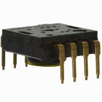
SENSOR OPTICAL MOUSE 8-DIP
Manufacturer
Avago Technologies US Inc.
Datasheet
1.ADNK-2610.pdf
(27 pages)
Specifications of ADNS-2610
Lead Free Status / RoHS Status
Lead free / RoHS Compliant
Lead Free Status / RoHS Status
Lead free / RoHS Compliant, Lead free / RoHS Compliant
Other names
516-1843
ADNS-2610
ADNS-2610


Overview of Optical Mouse Sensor Assembly
NOTE: Pin 1 of optical mouse sensor should be inserted
into the reference point of mechanical cutouts.
Figures 3 and 4 are shown with HDNS-2100, HDNS-2200
and HLMP-ED80-XX000.
Avago Technologies provides an IGES file drawing de-
scribing the base plate molding features for lens and PCB
alignment.
The components shown in Figure 5 interlock as they are
mounted onto defined features on the base plate.
The ADNS-2610 sensor is designed for mounting on a
through hole PCB, looking down. There is an aperture stop
and features on the package that align to the lens.
The HDNS-2100 lens provides optics for the imaging of
the surface as well as illumination of the surface at the
optimum angle. Features on the lens align it to the sensor,
base plate, and clip with the LED. The lens also has a large
round flange to provide a long creepage path for any ESD
events that occur at the opening of the base plate.
The HDNS-2200 clip holds the LED in relation to the lens.
The LED’s leads must be formed first before inserting into
the clip. Then, both LED and clip is loaded on the PCB. The
clip interlocks the sensor to the lens, and through the lens
to the alignment features on the base plate.
The HLMP-ED80-XX000 is recommended for illumination.
If used with the bin table (as shown in Figure 8), sufficient
illumination can be guaranteed.
12.60
Figure . Recommended PCB mechanical cutouts and spacing.
Figure 4. 2D assembly drawing of ADNS-2610 shown with the
HLMP-ED80 (top and side view).
Figure 5. Exploded view drawing.
0.496
14.58
0.574
Dimensions in mm/in.
(Side view)
(Top view)
+Y
11.10
0.437
10.58
0.417
0.049
1.25
0.293
7.45
PCB
+X
0
PLASTIC SPRING
SENSOR
0
0.357
9.06
18.94
0.746
0.039
1.00
HLMP-ED80-XX000
ADNS-2610 (Sensor)
Customer supplied PCB
HDNS-2100 (Lens)
HDNS-2200 (Clip)
Customer supplied base plate
with recommended alignment
features per IGES drawing
28.00
1.102
29.15
1.148
8X
32.46
1.278
φ
0.031
0.80
ESD LENS RING
CLIP
BASE PLATE ALIGNMENT POST
BASE PLATE
Clear Zone
0.053
1.35
ALL DIMENSIONS
φ
0.138
3.50
0.193
4.91
0.293
7.45
19.10
0.752
INCH
MM
13.73
0.541
13.82
0.54 4
Related parts for ADNS-2610
Image
Part Number
Description
Manufacturer
Datasheet
Request
R

Part Number:
Description:
Optical Mouse Sensor,DIP
Manufacturer:
Avago Technologies US Inc.
Datasheet:

Part Number:
Description:
Optical Mouse Sensor,DIP
Manufacturer:
Avago Technologies US Inc.
Datasheet:

Part Number:
Description:
Trim Lens For ADNS-3530
Manufacturer:
Avago Technologies US Inc.
Datasheet:

Part Number:
Description:
8 DIP SFF Navigation Sensor
Manufacturer:
Avago Technologies US Inc.
Datasheet:

Part Number:
Description:
Trim Lens For ADNS-5090
Manufacturer:
Avago Technologies US Inc.
Datasheet:

Part Number:
Description:
BLACK CLIP FOR ADNS-5000
Manufacturer:
Avago Technologies US Inc.
Datasheet:
Part Number:
Description:
Lens For ADNS-7630
Manufacturer:
Avago Technologies US Inc.
Datasheet:

Part Number:
Description:
Optical Mouse Sensor,DIP
Manufacturer:
Avago Technologies US Inc.
Datasheet:
Part Number:
Description:
Optical Mouse Sensor,DIP
Manufacturer:
Avago Technologies US Inc.
Datasheet:
Part Number:
Description:
Low Power Wireless LED Sensor
Manufacturer:
Avago Technologies US Inc.
Datasheet:

Part Number:
Description:
OPTOCOUPLER GATE DRV 2A 16-SOIC
Manufacturer:
Avago Technologies US Inc.
Datasheet:
Part Number:
Description:
OPTOCOUPLER 2CH 2.5A 16-SOIC
Manufacturer:
Avago Technologies US Inc.
Datasheet:

Part Number:
Description:
OPTOCOUPLER GATE DRV 0.4A 16SOIC
Manufacturer:
Avago Technologies US Inc.
Datasheet:

Part Number:
Description:
OPTOCOUPLER 2.0A 250KHZ 8-DIP
Manufacturer:
Avago Technologies US Inc.
Datasheet:

Part Number:
Description:
OPTOCOUPLER 2.0A 250KHZ GW 8-SMD
Manufacturer:
Avago Technologies US Inc.
Datasheet: