D3C-2210 Omron, D3C-2210 Datasheet - Page 2
D3C-2210
Manufacturer Part Number
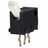
D3C-2210
Description
SUBMINIATURE BASIC SWITCH
Manufacturer
Omron
Series
D3Cr
Type
Detection Switchr
Specifications of D3C-2210
Circuit
SPDT
Switch Function
On-Mom
Contact Rating @ Voltage
0.1A @ 30VDC
Actuator Type
Angled Toggle (Detector)
Mounting Type
Through Hole
Termination Style
PC Pin
Operating Force
130gf
Contact Form
SPDT
Contact Rating
0.1 Amp
Actuator
Lever, Hinge
Body Style
Ultra Subminiature
Current, Rating
0.1 A
Dielectric Strength
250 VAC
Mounting Hole Size
1 mm
Number Of Poles
1
Special Features
Detection Switch, Toggle Actuator with Slide Contacts
Termination
Through Hole
Voltage, Rating
30 VDC
Lead Free Status / RoHS Status
Lead free / RoHS Compliant
Lead Free Status / RoHS Status
Lead free / RoHS Compliant
Other names
D3C2210
SW226
SW226
Available stocks
Company
Part Number
Manufacturer
Quantity
Price
Company:

Part Number:
D3C-2210
Manufacturer:
SAMSUNG
Quantity:
6 000


Engineering Data
■ Contact Specifications
Note: Minimum applicable loads are indicated by N standard
■ Switching Timing
■ Contact Form
Dimensions
Note: 1. Unless otherwise specified, all units are in millimeters and a tolerance of ±0.4 mm applies to all dimensions.
46
Specification
Material
Minimum applicable load
(see note)
D3C-1210/-2210
D3C-1220/-2220
Non-shorting Model
(2)
(1)
(3)
(NC)
(NO)
reference values. This value represents the failure rate at a
60% (λ
The equation λ
rate of 1/2,000,000 operations can be expected at a reliability
level of 60%.
F
P
60
Item
O
Detection Switch
) reliability level (JIS C5003).
P
1
OP2
1.6
SPDT
60
=0.5 x 10
+0.12
0
3.5
6
TTP
dia. hole
NO COM NC
(3)
4.7
(1)
Operating direction (B)
-6
Slide
Silver plated
1 mA at 5 VDC
/operations indicates that a failure
(2)
2.5 2.5
5.7±0.15
D3C
Shorting Model
(2)
(1)
(3)
8
6.7
8.7
(NC)
(NO)
4
Specification
FP
4.6 max.
0.8
1.5
–0.15
direction (A)
0
OP1
Operating
dia.
1-dia. hole
1R
OP FP
4±0.15
OP2
TTP
5.6
4.2
1.6
0.3
0.9
■ Mounting
All D3C switches may be panel mounted using M1.6 mounting
screws with plane washers or spring washers to securely mount the
switch. Tighten the screws to a torque of 4.9 to 9.8 x 10
■ PCB Layout
1
Note: The values for operating characteristics apply for operation in the
OF max.
RF min.
FP max.
OP1
OP2
TTP
Model
A direction (
operation in the B direction (
2.54
130 gf (100 gf)
10 gf (15 gf)
D3C-1210
Non-shorting Model
3.5 ± 0.3 mm
2.5 ± 0.3 mm
1.3 ± 0.4 mm
). The values in parentheses indicate those for
2.54
4.8 mm
(reference)
40 gf (30 gf)
M1.6 tap
5.7±0.1
D3C-1220
3 g (5 gf)
8
).
1.6 dia
4±0.1
Three, 1 dia. hole
130 gf (100 gf) 40 gf (30 gf)
10 gf (15 gf)
D3C-2210
4.2
Shorting Model
3.4 ± 0.3 mm
2.6 ± 0.3 mm
1.3 ± 0.4 mm
4.8 mm
-2
D3C-2220
3 g (5 gf)
N·m.
Related parts for D3C-2210
Image
Part Number
Description
Manufacturer
Datasheet
Request
R

Part Number:
Description:
SUBMINIATURE BASIC SWITCH
Manufacturer:
Omron
Datasheet:
Part Number:
Description:
SUBMINIATURE BASIC SWITCH
Manufacturer:
Omron
Datasheet:

Part Number:
Description:
G6S-2GLow Signal Relay
Manufacturer:
Omron Corporation
Datasheet:
Part Number:
Description:
Compact, Low-cost, SSR Switching 5 to 20 A
Manufacturer:
Omron Corporation
Datasheet:
Part Number:
Description:
Manufacturer:
Omron Corporation
Datasheet:
Part Number:
Description:
Manufacturer:
Omron Corporation
Datasheet:
Part Number:
Description:
Manufacturer:
Omron Corporation
Datasheet:
Part Number:
Description:
Manufacturer:
Omron Corporation
Datasheet:
Part Number:
Description:
Manufacturer:
Omron Corporation
Datasheet:
Part Number:
Description:
Manufacturer:
Omron Corporation
Datasheet: