D3C-2210 Omron, D3C-2210 Datasheet - Page 3
D3C-2210
Manufacturer Part Number
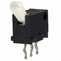
D3C-2210
Description
SUBMINIATURE BASIC SWITCH
Manufacturer
Omron
Series
D3Cr
Type
Detection Switchr
Specifications of D3C-2210
Circuit
SPDT
Switch Function
On-Mom
Contact Rating @ Voltage
0.1A @ 30VDC
Actuator Type
Angled Toggle (Detector)
Mounting Type
Through Hole
Termination Style
PC Pin
Operating Force
130gf
Contact Form
SPDT
Contact Rating
0.1 Amp
Actuator
Lever, Hinge
Body Style
Ultra Subminiature
Current, Rating
0.1 A
Dielectric Strength
250 VAC
Mounting Hole Size
1 mm
Number Of Poles
1
Special Features
Detection Switch, Toggle Actuator with Slide Contacts
Termination
Through Hole
Voltage, Rating
30 VDC
Lead Free Status / RoHS Status
Lead free / RoHS Compliant
Lead Free Status / RoHS Status
Lead free / RoHS Compliant
Other names
D3C2210
SW226
SW226
Available stocks
Company
Part Number
Manufacturer
Quantity
Price
Company:

Part Number:
D3C-2210
Manufacturer:
SAMSUNG
Quantity:
6 000


Precautions
Be sure to read the precautions and information common to all Snap Action and Detection Switches, contained in the Technical User’s Guide,
“Snap Action Switches, Technical Information” for correct use.
■ Correct Use
Mounting
Turn off the power supply before mounting or removing the switch,
wiring or performing maintenance or inspection. Failure to do so may
result in electric shock or burning.
Mount the switch onto a flat surface. Mounting on an uneven surface
may cause deformation of the switch, resulting in faulty operation or
breakage in the housing.
Application of Operation Force to the Lever
Apply operation forces to the lever in its operating direction. Applying
operating force to the lever in any other directions will damage the
switch or cause malfunction.
Mounting Plate
Use materials other than ABS or polycarbonate for the mounting
plate. Since grease is used within the switch, cracks may be caused
if grease from the switch comes in contact with such materials.
Using Microloads
Using a model for ordinary loads to switch microloads may result in
faulty operation. Instead, use the models that are designed for
microloads and that operate in the following range;
However, even when using microload models within the operating
range shown above, if inrush current or inductive voltage spikes
occur when the contact is opened or closed, then contact wear may
increase and so decrease the service life. Therefore, insert a contact
protection circuit where necessary.
Incorrect
24
12
30
5
0
0.1
0.16 mA
Inoperable
range
Correct
1mA
1
Operating range
Incorrect
10
100 mA
Current (mA)
100
Incorrect
1,000
■ Cautions
Terminal Connection
When soldering the lead wire to the terminals, first bind the lead wire
to the terminal and then apply the 60(Sn):40(Pb) solder to the termi-
nals. Complete soldering within 5s at a soldering iron temperature of
260°C. Soldering at a temperature exceeding 260°C, soldering for
more than 5 s, or repeated soldering will degrade the switch charac-
teristics.
When soldering the lead wire to the PCB terminal, pay careful atten-
tion so that the flux and solder liquid level does not exceed the PCB
level.
It is also recommended that you apply flux guard to the mounting sur-
face of the switch.
Detection Switch
Switch mounting surface
D3C
47
Related parts for D3C-2210
Image
Part Number
Description
Manufacturer
Datasheet
Request
R

Part Number:
Description:
SUBMINIATURE BASIC SWITCH
Manufacturer:
Omron
Datasheet:
Part Number:
Description:
SUBMINIATURE BASIC SWITCH
Manufacturer:
Omron
Datasheet:

Part Number:
Description:
G6S-2GLow Signal Relay
Manufacturer:
Omron Corporation
Datasheet:
Part Number:
Description:
Compact, Low-cost, SSR Switching 5 to 20 A
Manufacturer:
Omron Corporation
Datasheet:
Part Number:
Description:
Manufacturer:
Omron Corporation
Datasheet:
Part Number:
Description:
Manufacturer:
Omron Corporation
Datasheet:
Part Number:
Description:
Manufacturer:
Omron Corporation
Datasheet:
Part Number:
Description:
Manufacturer:
Omron Corporation
Datasheet:
Part Number:
Description:
Manufacturer:
Omron Corporation
Datasheet:
Part Number:
Description:
Manufacturer:
Omron Corporation
Datasheet: