AP-B Omron, AP-B Datasheet - Page 11
AP-B
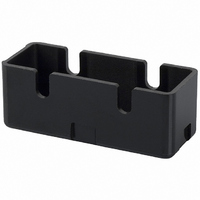
Manufacturer Part Number
AP-B
Description
SWITCH
Manufacturer
Omron
Type
Terminal Coverr
Specifications of AP-B
Accessory Type
Terminal Cover
Features
Phenolic Construction
Illumination
Not Illuminated
Height
20.2 mm
Length
53.8 mm
Mounting Style
Screw
Width
21 mm
Lead Free Status / RoHS Status
Lead free / RoHS Compliant
For Use With
SW234 - SWITCH 20A SHORT ROLLERSW233 - SWITCH 20A PANEL MOUNT PLUNGERSW232 - SWITCH 20A LONG ROLLERSW231 - SWITCH 20A LONG LEVERSW230 - SWITCH 20A PIN PLUNGERSW198 - SWITCH 15A LEVER LOW FORCESW197 - SWITCH 15A SHORT ROLLERSW196 - SWITCH 15A ROLLER LOW FORCESW195 - SWITCH 15A LEVER LOW FORCESW194 - SWITCH 15A PANEL MOUNT ROLLERSW193 - SWITCH 15A PANEL MOUNT ROLLERSW192 - SWITCH 15A PANEL MOUNT PIN PLUNSW191 - SWITCH 15A SPRING PLUNGERSW190 - SWITCH 15A PIN PLUNGER
For Use With/related Products
Omron A/Z Series
Lead Free Status / Rohs Status
Lead free / RoHS Compliant
Other names
APB
SW235
SW235


Note: 1. All drawings show the switches with screw terminals. For versions with solder terminals, remove the “-B” from the end of the part number.
Panel Mount Plunger
Z-15GQ-B Z-01HQ-B
Z-15HQ-B
Z-15EQ-B
Z-15GQ8-B *
Panel Mount Roller Plunger
Z-15GQ22-B Z-15EQ22-B
Z-15HQ22-B Z-10FQ22Y-B
Panel Mount Cross Roller Plunger
Z-15GQ21-B Z-15EQ21-B
Z-15HQ21-B
Note: Do not use the M12 mounting screw and
2. Unless otherwise specified, all units are in millimeters and a tolerance of ± 0.4 mm applies to all dimensions.
the case mounting hole at the same time,
or the case may be damaged.
Z-10FQY-B
Z-15GQ3-B *
* The external
OF
RF min.
PT max.
OT min.
MD max.
OP
dimensions of the
actuator vary.
Model
250 to 350 gf
Z-15GQ-B
0.05 mm
0.4 mm
5.5 mm
114 gf
PT
OP
15.5
16.3
PT
OP
PT
OP
4.2
13.1
16.3
15.5
16.3
*3
+0.075
-0.025
4.2
4.2
200 to 285 gf
*4
*3
+0.075
+0.075
-0.025
-0.025
Z-15HQ-B
0.025 mm
0.3 mm
5.5 mm
114 gf
16 dia.
4.36
25.4
23.3
16 dia.
16 dia.
49.2
+0.1
4.36
4.36
-0.05
± 0.25
± 0.1
23.3
25.4
23.3
25.4
11.9SR
49.2
49.2
dia.
+0.1
+0.1
-0.05
-0.05
± 0.25
± 0.1
± 0.25
± 0.1
11.9
*1
dia.
dia.
625 to 800 gf
21.8±0.8 mm
Z-15EQ-B
0.13 mm
4.2
0.8 mm
5.5 mm
11.9
11.9
114 gf
OF
RF min.
PT max.
OT min.
MD max.
OP
+0.075
-0.025
4.2
4.2
*1. Stainless-steel roller
*2. Two hexagonal nuts (3 t × 17 width
*3. Incomplete screw part with a maximum
Model
*1. Stainless-steel plunger
*2. Two hexagonal nuts (2 t × 14 width across flats)
*3. Two lock nuts (2 t × 15.6 width across flats)
*4. Incomplete screw part with a maximum length
+0.075
+0.075
dia. hole
across flats)
length of 1.5 mm.
-0.025
-0.025
*1. Stainless-steel roller
*2. Two hexagonal nuts (3 t × 17 width across flats)
*3. Incomplete screw part with a maximum length of 1.5 mm.
of 1.5 mm.
dia. hole
dia. hole
250 to 350 gf
Z-15GQ22-B
17.45
250 gf max.
3.58 mm
0.05 mm
Z-01HQ-B
0.4 mm
0.05 mm
114 gf
17.45
0.5 mm
5.5 mm
17.45
± 0.2
8.35 dia.
80 gf
12.7 dia. × 4.8 *1
General-purpose Basic Switch
± 0.2
± 0.2
M12 × 1
mounting
screw
M12 × 1
mounting screw
12.7 dia. × 4.8 *1
9.2
*2
M12 × 1
mounting
screw
9.2
9.2
*2
*2
*3
200 to 285 gf
Z-15HQ22-B
455 to 740 gf
0.025 mm
Z-10FQY-B
3.58 mm
0.3 mm
114 gf
0.8 mm
5.5 mm
0.1 mm
114 gf
Note: Do not use the M12 mounting screw
OF
RF min.
PT max.
OT min.
MD max.
OP
OF
RF min.
PT max.
OT min.
MD max.
OP
Model
Model
33.4±1.2 mm
Note: 1. Do not use the M12 mounting
and the case mounting hole at the same
time, or the case may be damaged.
2. On the model Z-15GQ3-B, PT
3. On the model Z-15GQ8-B,
4. On the model Z-15GQ8-B, the
625 to 800 gf
Z-15EQ22-B
Z-15GQ21-B
250 to 350 gf
625 to 800 gf
33.4±1.2 mm
Z-15EQ21-B
250 to 350 gf
18.8±0.8 mm
Z-15GQ3-B
screw and the case mounting hole
at the same time, or excessive
pulling force will be imposed on
the switch and the case and cover
may be damaged.
can be set to a value larger than
that for the Z-15GQ.
operating position can be adjust-
ed by providing a screw in the
plunger section.
M3 hole with a depth of 10 mm is
a through hole. Take precautions
so that no water or screw lock
agent penetrates into the hole.
3.58 mm
0.13 mm
3.58 mm
0.05 mm
3.58 mm
0.13 mm
0.8 mm
0.4 mm
0.8 mm
114 gf
114 gf
114 gf
4.2 mm
2.5 mm
2.2 mm
114 gf
33.4±1.2 mm
Z
Z-10FQ22Y-B
455 to 740 gf
200 to 285 gf
Z-15HQ21-B
250 to 350 gf
Z-15GQ8-B
0.025 mm
32.5±1 mm
3.55 mm
3.58 mm
0.1 mm
0.3 mm
0.05 mm
114 gf
1 mm
114 gf
0.5 mm
5.5 mm
114 gf
157
Related parts for AP-B
Image
Part Number
Description
Manufacturer
Datasheet
Request
R


Part Number:
Description:
G6S-2GLow Signal Relay
Manufacturer:
Omron Corporation
Datasheet:
Part Number:
Description:
Compact, Low-cost, SSR Switching 5 to 20 A
Manufacturer:
Omron Corporation
Datasheet:
Part Number:
Description:
Manufacturer:
Omron Corporation
Datasheet:
Part Number:
Description:
Manufacturer:
Omron Corporation
Datasheet:
Part Number:
Description:
Manufacturer:
Omron Corporation
Datasheet:
Part Number:
Description:
Manufacturer:
Omron Corporation
Datasheet:
Part Number:
Description:
Manufacturer:
Omron Corporation
Datasheet:
Part Number:
Description:
Manufacturer:
Omron Corporation
Datasheet: