AP-B Omron, AP-B Datasheet - Page 19
AP-B
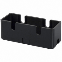
Manufacturer Part Number
AP-B
Description
SWITCH
Manufacturer
Omron
Type
Terminal Coverr
Specifications of AP-B
Accessory Type
Terminal Cover
Features
Phenolic Construction
Illumination
Not Illuminated
Height
20.2 mm
Length
53.8 mm
Mounting Style
Screw
Width
21 mm
Lead Free Status / RoHS Status
Lead free / RoHS Compliant
For Use With
SW234 - SWITCH 20A SHORT ROLLERSW233 - SWITCH 20A PANEL MOUNT PLUNGERSW232 - SWITCH 20A LONG ROLLERSW231 - SWITCH 20A LONG LEVERSW230 - SWITCH 20A PIN PLUNGERSW198 - SWITCH 15A LEVER LOW FORCESW197 - SWITCH 15A SHORT ROLLERSW196 - SWITCH 15A ROLLER LOW FORCESW195 - SWITCH 15A LEVER LOW FORCESW194 - SWITCH 15A PANEL MOUNT ROLLERSW193 - SWITCH 15A PANEL MOUNT ROLLERSW192 - SWITCH 15A PANEL MOUNT PIN PLUNSW191 - SWITCH 15A SPRING PLUNGERSW190 - SWITCH 15A PIN PLUNGER
For Use With/related Products
Omron A/Z Series
Lead Free Status / Rohs Status
Lead free / RoHS Compliant
Other names
APB
SW235
SW235


Note: 1. All drawings show the switches with screw terminals. For versions with solder terminals, remove the “-B” from the end of the part number.
Flexible Rod (Coil Spring)
Z-15GNJ55-B
Flexible Rod (Steel Wire)
Z-15HNJS55-B
2. Unless otherwise specified, all units are in millimeters and a tolerance of ± 0.4 mm applies to all dimensions.
(111.3)
(130.1)
100
(13.6)
(13.8)
43.4
16.3
16.3
38
± 0.4
4.2
4.2
(22)
+0.075
+0.075
-0.025
-0.025
PT
PT
4.36
4.36
25.4
25.4
49.2
49.2
23.3
23.3
+0.1
+0.1
-0.05
-0.05
30 Operating range *2
30 Operating range *2
± 0.1
± 0.1
Four, M3 set screws
with hexagonal holes
± 0.25
± 0.25
Rubber cap
Rubber cap
dia.
dia.
11.9
11.9
4.2
4.2
+0.075
+0.075
-0.025
-0.025
dia. hole
dia. hole
1-dia. stainless
steel wire *3
Nylon rod
12 dia.
12 dia.
9.2
9.2
6.1 dia.
3.2 dia.
17.45
17.45
*1
*1
General-purpose Basic Switch
± 0.2
± 0.2
*1. Operation is possible in any direction other than the
*2. Use only the area within the top 30 mm of the rod as
*1. Operation is possible in any direction other than the axial
*2. Use only the area within the top 30 mm of the rod as the
*3. The steel wire can be replaced if damaged.
axial direction (indicated by the arrow
the operating part. (Do not use the area that falls within
80 mm from the mounting hole as the operating part.
Using this area may cause damage to the nylon rod.
direction (indicated by the arrow
operating part. (Do not use the area that falls within 100
mm from the mounting hole as the operating part.
Using this area may cause damage to the steel wire.)
(Model: Lever for HNJS55)
OF max.
PT max.
OF max.
PT max.
TT max.
).
).
Z
(25 mm)
(20 mm)
40 mm
15 gf
50 gf
165
Related parts for AP-B
Image
Part Number
Description
Manufacturer
Datasheet
Request
R


Part Number:
Description:
G6S-2GLow Signal Relay
Manufacturer:
Omron Corporation
Datasheet:
Part Number:
Description:
Compact, Low-cost, SSR Switching 5 to 20 A
Manufacturer:
Omron Corporation
Datasheet:
Part Number:
Description:
Manufacturer:
Omron Corporation
Datasheet:
Part Number:
Description:
Manufacturer:
Omron Corporation
Datasheet:
Part Number:
Description:
Manufacturer:
Omron Corporation
Datasheet:
Part Number:
Description:
Manufacturer:
Omron Corporation
Datasheet:
Part Number:
Description:
Manufacturer:
Omron Corporation
Datasheet:
Part Number:
Description:
Manufacturer:
Omron Corporation
Datasheet: