D5A-3210 Omron, D5A-3210 Datasheet - Page 5
D5A-3210
Manufacturer Part Number
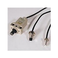
D5A-3210
Description
M8 1micPn Plngr Sld St .49N 1m
Manufacturer
Omron
Datasheet
1.D5A-7413.pdf
(8 pages)
Specifications of D5A-3210
Contact Rating
10 mAmps at 5 VoltsDC to 24 VoltsDC
Operating Force
0.49 N
On Travel
1.5 mm
Termination Style
Screw
Lead Free Status / Rohs Status
Lead free / RoHS Compliant


Safety Precautions
Refer to Safety Precautions for All Limit Switches.
Handling of Fiber Cable
Mounting
• Do not pull or impose any force exceeding 29.42 N on the fiber
• Make sure that the bending radius of the fiber cable is as large as
• The 40-mm portion of the fiber cable on the connector end as
• Do not impose compressing loads on the fiber cable.
• The fiber cable can be cut with OMRON’s E39-F4 Cutting Tool.
• Do not impose any force exceeding 29.42 N on the cable, otherwise
• The screw sections of cases for M5, M8, and M16 types have
• For the mounting dimensions, refer to the following figures and
• Do not tighten the nut with too much force. Be sure to apply the
cable.
possible and at least R20 mm.
shown below must not be bent.
the cord may break. Make sure that the bending radius of the cable
is at least 20 mm.
special dimensions. Do not use the mounting dimensions specified
for standard types.
tables.
torque shown in this table.
Type
Limit
M5
M8
M16
Slim
Precautions for Correct Use
Size
A (Mounting hole)
B (Panel thickness)
C
(Toothed lock washer)
Size
A Mounting pitch
B
Tapping
Mounting hole
Type
Fiber cable
Nylon clip
R20 mm min.
Type
40 mm min.
Appropriate tightening torque
3 to 10 mm
10 mm dia.
mm dia.
5.2±0.1
0.29 N·m max. (M2.6 screw)
0.98 N·m max.
2.94 N·m max.
9.81 N·m max.
1.47 N·m max. (M4 screw)
M5
2.8
12±0.2 mm
±0.2
0
M2.6
Slim
8.2±0.1 mm dia.
Contact
output
5 to 8
mm dia.
mm
15 mm dia.
M8
Solid-state
5 to 13
output
mm
4.2
20±0.2 mm
±0.2
0
Limit
10 to 17 mm
26 mm dia.
M4
16.2±0.1
mm dia.
mm dia.
M16
Connection of Contact Output
Consideration of polarity is not required.
Connection of Solid-state Output
Note: The lead wire colors of the D5A have been changed in compliance with
[Example]
(1) In the above circuit, suppose the MY relay rated at 12 VDC is used as the
(2) However, if the relay rated at 24 VDC is employed, the must operate voltage
• When mounting the Switch to a panel, be sure to use the toothed
• Be sure to connect the load to the power source in series.
• The operating state of the Switch can be checked by the LED
• The output residual voltage is approximately 3 V. Therefore,
• When a solid-state circuit is turned OFF, leakage current of 0.15
lock washer attached as an accessory (to M5, M8, and M16 types
only). Use the washer on the panel surface opposite the object to
be detected by the Switch.
operation indicator (lights when the Switch is in operation)
incorporated in the solid-state output circuit.
exercise care when selecting the load and setting the supply
voltage. The residual voltage, however, can be easily calculated
because it is almost constant and is free from the influence of
fluctuation in the load current.
mA (max.) flows, causing some voltages to remain in the load. For
this reason, be sure to check the must release voltage of the load
before using it.
load. Since the must operate voltage of the relay is 80% or less than the
rated voltage, it is 12 × 0.8 = 9.6 V. The supply voltage, in turn, is 3 + 9.6 =
12.6 V.
Therefore, the relay may not operate with a 12 V power source.
and supply voltage of the relay are respectively 19.2 V and 22.2 V. The relay
therefore can operate with a 24 V power source.
the latest applicable JIS standards.
Colors in parentheses are previous ones.
D5A
D5A
D5A
Object
to be
detected
Brown (White)
Blue (Black)
Load
Load
100 mA max.
Toothed lock washer
Nut
5 to 24 VDC
12 VDC
10 mA
24 VAC
10 mA
D5A
5
Related parts for D5A-3210
Image
Part Number
Description
Manufacturer
Datasheet
Request
R

Part Number:
Description:
LmitSw3micTpPlngrSldSt 3.9N 5m
Manufacturer:
Omron
Datasheet:

Part Number:
Description:
M8 1micPin Plngr Cntact .49 1m
Manufacturer:
Omron
Datasheet:

Part Number:
Description:
G6S-2GLow Signal Relay
Manufacturer:
Omron Corporation
Datasheet:
Part Number:
Description:
Compact, Low-cost, SSR Switching 5 to 20 A
Manufacturer:
Omron Corporation
Datasheet:
Part Number:
Description:
Manufacturer:
Omron Corporation
Datasheet:
Part Number:
Description:
Manufacturer:
Omron Corporation
Datasheet:
Part Number:
Description:
Manufacturer:
Omron Corporation
Datasheet:
Part Number:
Description:
Manufacturer:
Omron Corporation
Datasheet:
Part Number:
Description:
Manufacturer:
Omron Corporation
Datasheet:
Part Number:
Description:
Manufacturer:
Omron Corporation
Datasheet: