D5A-3210 Omron, D5A-3210 Datasheet - Page 6
D5A-3210
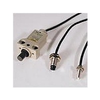
Manufacturer Part Number
D5A-3210
Description
M8 1micPn Plngr Sld St .49N 1m
Manufacturer
Omron
Datasheet
1.D5A-7413.pdf
(8 pages)
Specifications of D5A-3210
Contact Rating
10 mAmps at 5 VoltsDC to 24 VoltsDC
Operating Force
0.49 N
On Travel
1.5 mm
Termination Style
Screw
Lead Free Status / Rohs Status
Lead free / RoHS Compliant


Series Connection of Switches
The Solid-state Output-type Switches must not be connected in
series. To obtain the same effect as a series connection, form an AND
gate with a relay inserted between the Switch and load.
Parallel Connection of Switches
Connection to Power Source
The core wire colors have been changed to meet new standards. Make sure
that the wires are connected correctly.
• In principle, two or more D5A's should not be used in an OR
• However, they can be connected in parallel provided that both
• Be sure to connect the Switch to the power source via the load. If
• Correctly connect the white and black lead wires to the positive and
configuration.
switches A and B in the above figure do not operate at the same
time and that the load does not have to be kept energized. In this
circuit, however, the leakage current is increased, multiplied by the
number of Switches connected in parallel. Consequently, the
Switch may not release properly. To keep the load energized,
connect a relay to each of the Switches as shown below.
directly connected to the power source, the internal elements of the
Switch may be damaged.
negative sides, respectively, of the power source. Although the
D5A will not be damaged even if the polarity is reversed by mistake,
if this happens, the Switch maintains the ON state (i.e., the contact
is kept open) regardless of the presence or absence of the object
to be detected.
D5A
D5A
D5A
D5A
(A)
Brown
(White)
Brown
(White)
Blue
(Black)
Blue
(Black)
Brown (White) Brown (White)
Blue (Black)
Blue
(Black)
Brown
(White)
Brown (White)
Blue (Black)
Brown (White)
Blue (Black)
Brown (White)
Blue (Black)
D5A
D5A
(B)
Brown
(White)
Brown
(White)
Blue
(Black)
Blue
(Black)
Blue (Black)
Always close
circuit
Load
Load
Load
Load
Load
Others
• Adjust the mounting of the D5A until the stroke of the pin plunger
• The harder the material for the dog and the more solidly the
• When a limit switch type (D5A-8 @@@, D5A-9 @@@) is used, apply
• Be sure to use dogs made of hard materials for bevel or top
• Do not fail to provide a stopper so as to prevent the enclosure of the
• Attach an appropriate cover for the protection of the D5A from
• Exercise care that excessive force is not applied to the ceramic
• Do not mount the Switch with its nameplate facing downwards (i.e.,
and top plunger is aligned with the stroke of the operating body.
Special attention should be paid to the ceramic pushbutton unit. It
might be damaged if undue shock is applied.
mounting base is fitted, the more accurately a minute displacement
is detected.
grease to the dog to reduce friction between it and the plunger.
Do not apply grease to pin plungers, otherwise the grease may
stick to the contacts or generate gas that may cause contact
failures.
plungers and apply grease to the surface of the dogs. The hardness
(Hv) of a bevel plunger is 2,000 or over, for which it is
recommended that a dog that has an Hv value of 1,000 or less be
used.
D5A from being used as the stoppers.
machining oil or cuttings. No protective cover is, however, provided
together with the Switch.
plunger of M5, M8, or slim type.
If the possibility exists that strong shock may be applied to the
plunger when the Switch is being mounted, use a protective cap.
The plunger may not release if it is depressed with too great a force.
Set its stroke by referring to the OT value indicated in Operating
Characteristics.
in the direction of gravity), otherwise the oil drain hole will not work
effectively.
Stopper
Dog
Switch
M5, M8
Oil drain hole
Nameplate
Slim
Stopper
Dog
D5A
6
Related parts for D5A-3210
Image
Part Number
Description
Manufacturer
Datasheet
Request
R

Part Number:
Description:
LmitSw3micTpPlngrSldSt 3.9N 5m
Manufacturer:
Omron
Datasheet:

Part Number:
Description:
M8 1micPin Plngr Cntact .49 1m
Manufacturer:
Omron
Datasheet:

Part Number:
Description:
G6S-2GLow Signal Relay
Manufacturer:
Omron Corporation
Datasheet:
Part Number:
Description:
Compact, Low-cost, SSR Switching 5 to 20 A
Manufacturer:
Omron Corporation
Datasheet:
Part Number:
Description:
Manufacturer:
Omron Corporation
Datasheet:
Part Number:
Description:
Manufacturer:
Omron Corporation
Datasheet:
Part Number:
Description:
Manufacturer:
Omron Corporation
Datasheet:
Part Number:
Description:
Manufacturer:
Omron Corporation
Datasheet:
Part Number:
Description:
Manufacturer:
Omron Corporation
Datasheet:
Part Number:
Description:
Manufacturer:
Omron Corporation
Datasheet: