G3PA-220B-VD DC5-24 Omron, G3PA-220B-VD DC5-24 Datasheet - Page 15
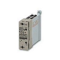
G3PA-220B-VD DC5-24
Manufacturer Part Number
G3PA-220B-VD DC5-24
Description
SOLID STATE RELAY
Manufacturer
Omron
Series
G3PAr
Specifications of G3PA-220B-VD DC5-24
Circuit
SPST-NO (1 Form A)
Output Type
AC, Zero Cross
Load Current
20A
Voltage - Input
4 ~ 30VDC
Voltage - Load
19 ~ 264 V
Mounting Type
DIN Rail
Termination Style
Screw Terminal
Package / Case
SSR with Integrated Heatsink
Control Voltage Range
5 V to 24 V
Load Voltage Rating
200 V
Load Current Rating
20 A
Mounting Style
DIN Rail
Lead Free Status / RoHS Status
Lead free / RoHS Compliant
On-state Resistance
-
Lead Free Status / Rohs Status
Lead free / RoHS Compliant
Other names
G3PA-220B-VDDC5-24
G3PA220BVDDC524
G3PA220BVDDC524


Close Mounting
SSR Mounting Pitch
Panel Mounting
Relationship between SSRs and Ducts
Ventilation
If the air inlet or air outlet has a filter, clean the filter regularly to
prevent it from clogging and ensure an efficient flow of air.
Do not locate any objects around the air inlet or air outlet, otherwise
the objects may obstruct the proper ventilation of the control panel.
Do not surround the SSR
with ducts, otherwise the
heat radiation of the SSR
will be adversely affected.
Duct Height
Mounting direction
Space between
SSRs
Vertical direction
G3PA
Air inlet
80 mm min.
Duct or airflow obstruction
Duct or
airflow
obstruction
Vertical
direction
Duct or
airflow
obstruction
G3PA
SSR
(At a rated ambient temperature of 40°C).
ALL DIMENSIONS SHOWN ARE IN MILLIMETERS.
To convert millimeters into inches, multiply by 0.03937. To convert grams into ounces, multiply by 0.03527.
Duct or
air flow
obstruction
Countermeasure (1)
Use short ducts.
Be aware of air flow
50 mm max.
In the interest of product improvement, specifications are subject to change without notice.
min.
(A height of no
more than half
the SSR's height is
recommended.)
G3PA
G3PA
Close Mounting
Countermeasure (2)
If the ducts cannot be
shortened, place the SSR
on a metal base so that it
is not surrounded by the
ducts.
60 mm min.
Ventilation
outlet
Between duct
or airflow
obstruction
and SSR
30 mm min.
G3PA
Airflow
G3PA
A heat exchanger, if used, should be located in front of the SSR Units
to ensure the efficiency of the heat exchanger.
Please reduce the ambient temperature of SSRs.
The rated load current of an SSR is measured at an ambient
temperature of 25 or 40 °C.
An SSR uses a semiconductor in the output element. This causes
the temperature inside the control panel to increase due to heating
resulting from the passage of electrical current through the load. To
restrict heating, attach a fan to the ventilation outlet or air inlet of the
control panel to ventilate the panel. This will reduce the ambient
temperature of the SSRs and thus increase reliability. (Generally,
each 10°C reduction in temperature will double the expected life.)
Example: For 10 SSRs with load currents of 20 A,
If there are other instruments that generate heat in the control
panel other than SSRs, additional ventilation will be required.
Required number of fans
per SSR
Load current (A)
Ambient temperature of control panel: 30°C
0.31 x 10 = 3.1
Thus, 4 fans would be required.
Size of fans: 92 mm
0.16
10 A
2
, Air volume: 0.7 m
0.31
20 A
0.47
30 A
3
/min,
0.62
40 A
G3PA
0.93
60 A
15
Related parts for G3PA-220B-VD DC5-24
Image
Part Number
Description
Manufacturer
Datasheet
Request
R

Part Number:
Description:
SOLID STATE RELAY
Manufacturer:
Omron
Datasheet:

Part Number:
Description:
G6S-2GLow Signal Relay
Manufacturer:
Omron Corporation
Datasheet:
Part Number:
Description:
Compact, Low-cost, SSR Switching 5 to 20 A
Manufacturer:
Omron Corporation
Datasheet:
Part Number:
Description:
Manufacturer:
Omron Corporation
Datasheet:
Part Number:
Description:
Manufacturer:
Omron Corporation
Datasheet:
Part Number:
Description:
Manufacturer:
Omron Corporation
Datasheet:
Part Number:
Description:
Manufacturer:
Omron Corporation
Datasheet:
Part Number:
Description:
Manufacturer:
Omron Corporation
Datasheet:
Part Number:
Description:
Manufacturer:
Omron Corporation
Datasheet: