G9EA-1-B DC100 Omron, G9EA-1-B DC100 Datasheet - Page 2
G9EA-1-B DC100
Manufacturer Part Number
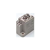
G9EA-1-B DC100
Description
DC Power Relay
Manufacturer
Omron
Series
G9EA-1r
Datasheet
1.G9EA-1-B_DC24.pdf
(10 pages)
Specifications of G9EA-1-B DC100
Relay Type
General Purpose
Contact Form
SPST-NO (1 Form A)
Contact Rating (current)
60A
Switching Voltage
400VDC - Max
Coil Type
Standard
Coil Current
53.6mA
Coil Voltage
100VDC
Turn On Voltage (max)
75 VDC
Turn Off Voltage (min)
8 VDC
Mounting Type
Chassis Mount
Termination Style
Screw Terminal
Circuit
SPST-NO (1 Form A)
Contact Rating @ Voltage
60A @ 400VDC
Control On Voltage (max)
75 VDC
Control Off Voltage (min)
8 VDC
Load Voltage Rating
400 VDC
Load Current Rating
60 A
Lead Free Status / RoHS Status
Lead free / RoHS Compliant
Lead Free Status / RoHS Status
Lead free / RoHS Compliant
Other names
G9EA-1-BDC100
G9EA1BDC100
G9EA1BDC100


Specifications
■ Ratings
Coil
Note: 1. The figures for the rated current and coil resistance are for a coil temperature of 23°C and have a tolerance of ±10%.
Contacts
■ Characteristics
Note: 1. The above values are initial values at an ambient temperature of 23°C unless otherwise specified.
2
12 VDC
24 VDC
48 VDC
60 VDC
100 VDC
Rated load
Rated carry current
Maximum switching voltage
Maximum switching current
Contact resistance (See note 2.)
Contact voltage drop
Operate time
Release time
Insulation resistance
(See note 3.)
Dielectric strength
Impulse withstand voltage (See note 4.)
Vibration resistance
Shock resistance
Mechanical endurance (See note 5.)
Electrical endurance (See note 6.)
Short-time carry current
Maximum interruption current
Overload interruption
Reverse polarity interruption
Ambient operating temperature
Ambient operating humidity
Weight
Rated voltage
2. The figures for the operating characteristics are for a coil temperature of 23°C.
3. The figure for the maximum voltage is the maximum voltage that can be applied to the relay coil for period of 10 minutes at an ambient
2. The contact resistance was measured with 1 A at 5 VDC using the voltage drop method.
3. The insulation resistance was measured with a 500-VDC megohmmeter.
4. The impulse withstand voltage was measured with a JEC-212 (1981) standard impulse voltage waveform (1.2 × 50 μs).
5. The mechanical endurance was measured at a switching frequency of 3,600 operations/hr.
6. The electrical endurance was measured at a switching frequency of 60 operations/hr.
temperature of 23°C. It does not apply to continuous operation.
DC Power Relays (60-A, 100-A Models)
417 mA
208 mA
102 mA
86.2 mA
53.6 mA
Item
Rated current
Between coil and contacts
Between contacts of the same
polarity
Between coil and contacts
Between contacts of the same
polarity
Destruction
Malfunction
Destruction
Malfunction
Item
28.8 Ω
115.2 Ω
469.3 Ω
695.7 Ω
1,864 Ω
Coil resistance
60 A at 400 VDC, 100 A at 120 VDC
60 A
400 V
100 A
75% max. of rated
voltage
Must-operate
G9EA-1(-B)
30 mΩ max. (0.6 mΩ typical)
0.1 V max.
(for a carry current of 60 A)
50 ms max.
30 ms max.
1,000 MΩ min.
1,000 MΩ min.
2,500 VAC, 1 min
2,500 VAC, 1 min
4,500 V
10 to 55 to 10 Hz, 0.75-mm single amplitude (Acceleration: 2.94 to 88.9 m/s
10 to 55 to 10 Hz, 0.75-mm single amplitude (Acceleration: 2.94 to 88.9 m/s
490 m/s
196 m/s
200,000 ops. min.
120 VDC, 100 A, 3,000 ops. min.
400 VDC, 60 A, 3,000 ops. min.
400 VDC, 30 A, 30,000 ops. min.
100 A (10 min)
600 A at 300 VDC (5 times)
180 A at 400 VDC (100 times min.)
–60 A at 200 VDC (1,000 times min.)
–40 to 70°C (with no icing or condensation)
5% to 85%
Approx. 310 g
G9EA-1
voltage
2
2
G9EA-1(-B)
8% min. of rated
voltage
Must-release
Resistive load
voltage
30 A at 400 VDC
100 A
400 V
30 A
130% of rated volt-
age
Maximum voltage
10 mΩ max. (0.3 mΩ typical)
0.1 V max.
(for a carry current of 100 A)
400 VDC, 30 A, 1,000 ops. min.
120 VDC, 30 A, 2,500 ops. min.
—
150 A (10 min)
—
100 A at 120 VDC (150 times min.)
—
(See note 3.)
G9EA-1(-B)-CA
G9EA-1(-B)-CA
Approx. 5 W
Approx. 5.2 W
Approx. 5.4 W
consumption
Power
2
2
)
)
Related parts for G9EA-1-B DC100
Image
Part Number
Description
Manufacturer
Datasheet
Request
R

Part Number:
Description:
DC Power Relay
Manufacturer:
Omron
Datasheet:
Part Number:
Description:
DC Power Relay
Manufacturer:
Omron
Datasheet:

Part Number:
Description:
DC Power Relay
Manufacturer:
Omron
Datasheet:

Part Number:
Description:
DC POWER RELAY
Manufacturer:
Omron
Datasheet:
Part Number:
Description:
DC POWER RELAY
Manufacturer:
Omron
Datasheet:
Part Number:
Description:
DC POWER RELAY
Manufacturer:
Omron
Datasheet:
Part Number:
Description:
DC POWER RELAY
Manufacturer:
Omron
Datasheet:
Part Number:
Description:
DC Power Relay
Manufacturer:
Omron
Datasheet:
Part Number:
Description:
DC Power Relay
Manufacturer:
Omron
Datasheet:
Part Number:
Description:
DC Power Relay
Manufacturer:
Omron
Datasheet:
Part Number:
Description:
DC Power Relay
Manufacturer:
Omron
Datasheet:
Part Number:
Description:
DC Power Relay
Manufacturer:
Omron
Datasheet:
Part Number:
Description:
DC Power Relay
Manufacturer:
Omron
Datasheet:
Part Number:
Description:
DC Power Relay
Manufacturer:
Omron
Datasheet: