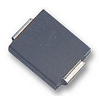
ES1C-E3/5AT Vishay, ES1C-E3/5AT Datasheet - Page 3

ES1C-E3/5AT
Manufacturer Part Number
ES1C-E3/5AT
Description
DIODE 1A 150V 15NS DO-214AC
Manufacturer
Vishay
Specifications of ES1C-E3/5AT
Diode Type
Standard
Voltage - Forward (vf) (max) @ If
920mV @ 1A
Voltage - Dc Reverse (vr) (max)
150V
Current - Average Rectified (io)
1A
Current - Reverse Leakage @ Vr
5µA @ 150V
Speed
Fast Recovery =< 500ns, > 200mA (Io)
Reverse Recovery Time (trr)
25ns
Mounting Type
Surface Mount
Package / Case
DO-214AC, SMA
Repetitive Reverse Voltage Vrrm Max
150V
Forward Current If(av)
1A
Forward Voltage Vf Max
920mV
Reverse Recovery Time Trr Max
15ns
Forward Surge Current Ifsm Max
30A
Product
Ultra Fast Recovery Rectifier
Configuration
Single
Reverse Voltage
150 V
Forward Voltage Drop
0.92 V
Recovery Time
25 ns
Forward Continuous Current
1 A
Max Surge Current
30 A
Reverse Current Ir
5 uA
Mounting Style
SMD/SMT
Maximum Operating Temperature
+ 150 C
Minimum Operating Temperature
- 55 C
Lead Free Status / RoHS Status
Lead free / RoHS Compliant
Capacitance @ Vr, F
-
Lead Free Status / Rohs Status
Details
ES1A thru ES1D
Vishay General Semiconductor
PACKAGE OUTLINE DIMENSIONS in inches (millimeters)
www.vishay.com
652
Figure 3. Typical Instantaneous Forward Characteristics
1000
0.01
100
100
0.1
10
0.1
10
Figure 4. Typical Reverse Leakage Characteristics
1
1
0.2
0
Percent of Rated Peak Reverse Voltage (%)
T
J
0.4
= 125 °C
Instantaneous Forward Voltage (V)
20
0.065 (1.65)
0.049 (1.25)
0.060 (1.52)
0.030 (0.76)
0.090 (2.29)
0.078 (1.98)
T
0.6
J
T
T
= 150 °C
J
J
40
= 150 °C
= 100 °C
PDD-Americas@vishay.com, PDD-Asia@vishay.com, PDD-Europe@vishay.com
0.8
For technical questions within your region, please contact one of the following:
T
T
T
J
T
J
J
= 25 °C
60
J
= 125 °C
= 25 °C
= 100 °C
1.0
DO-214AC (SMA)
0.194 (4.93)
0.177 (4.50)
0.157 (3.99)
0.208 (5.28)
80
Cathode Band
1.2
0.008 (0.203)
0 (0)
100
1.4
0.110 (2.79)
0.100 (2.54)
0.012 (0.305)
0.006 (0.152)
0.066 (1.68)
100
12
10
10
14
0.060 (1.52)
8
6
4
2
0
1
MIN.
0.1
0.1
MIN.
Mounted on 0.2 x 0.2" (5 x 7 mm)
Copper Pad Areas
Figure 5. Typical Junction Capacitance
Mounting Pad Layout
Figure 6. Typical Thermal Impedance
t - Pulse Duration (s)
Reverse Voltage (V)
0.208 (5.28)
1
1
REF.
0.074 (1.88)
MAX.
10
10
Document Number: 88586
T
f = 1.0 MHz
V
J
sig
= 25 °C
= 50 mVp-p
Revision: 27-Aug-08
100
100


