SL12-E3/5AT Vishay, SL12-E3/5AT Datasheet
SL12-E3/5AT
Specifications of SL12-E3/5AT
Available stocks


Related parts for SL12-E3/5AT


SL12-E3/5AT Summary of contents
Page 1
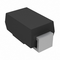
... Q101 qualified), meets JESD 201 class 2 whisker test Polarity: Color band denotes the cathode end SYMBOL V RRM V RMS 105 °C (Fig F(AV) I FSM dV/ STG SL12 & SL13 Vishay General Semiconductor dc-to-dc converters, and SL12 SL13 SL2 SL3 1 000 - 125 - 150 www.vishay.com ...
Page 2
... SL12 & SL13 Vishay General Semiconductor ELECTRICAL CHARACTERISTICS (T PARAMETER Maximum instantaneous forward voltage at Maximum DC reverse current (1) at rated DC blocking voltage Note: (1) Pulse test: 300 µs pulse width duty cycle THERMAL CHARACTERISTICS (T PARAMETER (1) Maximum thermal resistance Note: (1) P.C.B. mounted on 0.2 x 0.2" (5.0 x 5.0 mm) copper pad areas ...
Page 3
... MIN. 0.110 (2.79) 0.100 (2.54) 0.177 (4.50) 0.157 (3.99) 0.060 (1.52) 0.012 (0.305) 0.006 (0.152) 0.008 (0.203) 0 (0) 0.208 (5.28) 0.194 (4.93) SL12 & SL13 Vishay General Semiconductor ° 1.0 MHz mVp-p sig 1 10 Reverse Voltage (V) Figure 5. Typical Junction Capacitance Mounting Pad Layout 0 ...
Page 4
... Vishay product could result in personal injury or death. Customers using or selling Vishay products not expressly indicated for use in such applications their own risk and agree to fully indemnify and hold Vishay and its distributors harmless from and against any and all claims, liabilities, expenses and damages arising or resulting in connection with such use or sale, including attorneys fees, even if such claim alleges that Vishay or its distributor was negligent regarding the design or manufacture of the part ...