BYW80-200G ON Semiconductor, BYW80-200G Datasheet - Page 2
BYW80-200G
Manufacturer Part Number
BYW80-200G
Description
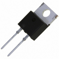
DIODE ULT FAST 200V 7A TO-220AC
Manufacturer
ON Semiconductor
Series
SWITCHMODE™r
Datasheet
1.BYW80-200G.pdf
(4 pages)
Specifications of BYW80-200G
Voltage - Forward (vf) (max) @ If
1.25V @ 22A
Voltage - Dc Reverse (vr) (max)
200V
Current - Average Rectified (io)
8A
Current - Reverse Leakage @ Vr
10µA @ 200V
Diode Type
Standard
Speed
Fast Recovery =< 500ns, > 200mA (Io)
Reverse Recovery Time (trr)
35ns
Mounting Type
Through Hole
Package / Case
TO-220-2, TO-220AC
Product
Ultra Fast Recovery Rectifier
Configuration
Single
Reverse Voltage
200 V
Forward Voltage Drop
1.25 V at 22 A
Recovery Time
35 ns
Forward Continuous Current
16 A
Max Surge Current
100 A
Reverse Current Ir
10 uA
Mounting Style
Through Hole
Maximum Operating Temperature
+ 175 C
Minimum Operating Temperature
- 65 C
Lead Free Status / RoHS Status
Lead free / RoHS Compliant
Capacitance @ Vr, F
-
Lead Free Status / Rohs Status
Lead free / RoHS Compliant
Available stocks
Company
Part Number
Manufacturer
Quantity
Price
Company:

Part Number:
BYW80-200G
Manufacturer:
ON Semiconductor
Quantity:
977
Company:
Part Number:
BYW80-200G
Manufacturer:
SHARP
Quantity:
20 000


1. Pulse Test: Pulse Width ≤ 300 ms, Duty Cycle ≤ 2.0%.
THERMAL CHARACTERISTICS
ELECTRICAL CHARACTERISTICS
Maximum Thermal Resistance, Junction−to−Case
Maximum Instantaneous Forward Voltage (Note 1)
Maximum Instantaneous Reverse Current (Note 1)
Maximum Reverse Recovery Time
100
(i
(i
(Rated dc Voltage, T
(Rated dc Voltage, T
(I
(I
7.0
5.0
3.0
2.0
1.0
0.7
0.5
0.3
0.2
0.1
70
50
30
20
10
F
F
F
F
= 7.0 Amps, T
= 22 Amps, T
= 1.0 Amp, di/dt = 50 Amps/ms)
= 0.5 Amp, i
0.2
0.3
Figure 1. Typical Forward Voltage
T
J
0.4
= 175°C
R
v
F,
C
C
= 1.0 Amp, I
INSTANTANEOUS VOLTAGE (VOLTS)
= 25°C)
= 100°C)
0.5
J
J
= 100°C)
= 25°C)
0.6
REC
100°C
0.7
= 0.25 Amp)
Rating
0.8
25°C
0.9
1.0
http://onsemi.com
1.1
1.2
2
1000
0.01
100
1.0
0.1
9.0
8.0
7.0
6.0
5.0
4.0
3.0
2.0
1.0
10
10
0
0
140
* The curves shown are typical for the highest voltage device in the
grouping. Typical reverse current for lower voltage selections can be
estimated from these same curves if V
20
Figure 2. Typical Reverse Current*
Figure 3. Current Derating, Case
SQUARE WAVE
40
Symbol
150
R
v
V
i
t
qJC
R
rr
F
R
60
, REVERSE VOLTAGE (VOLTS)
T
C
, CASE TEMPERATURE (°C)
80
T
dc
J
100°C
= 175°C
25°C
100
160
R
is sufficiently below rated V
Values
120
0.85
1.25
0.01
3.0
35
25
1
RATED V
140
170
160
R
APPLIED
180
°C/W
Unit
mA
R
ns
V
.
200
180
Related parts for BYW80-200G
Image
Part Number
Description
Manufacturer
Datasheet
Request
R

Part Number:
Description:
8A 200V Ultrafast Rectifier
Manufacturer:
ON Semiconductor
Datasheet:

Part Number:
Description:
Standard Avalanche Sinterglass Diode
Manufacturer:
Vishay Intertechnology
Datasheet:
Part Number:
Description:
ON Semiconductor [VOLTAGE REGULATOR]
Manufacturer:
ON Semiconductor
Datasheet:
Part Number:
Description:
357-036-542-201 CARDEDGE 36POS DL .156 BLK LOPRO
Manufacturer:
ON Semiconductor
Datasheet:
Part Number:
Description:
357-036-542-201 CARDEDGE 36POS DL .156 BLK LOPRO
Manufacturer:
ON Semiconductor
Datasheet:
Part Number:
Description:
357-036-542-201 CARDEDGE 36POS DL .156 BLK LOPRO
Manufacturer:
ON Semiconductor
Datasheet:
Part Number:
Description:
357-036-542-201 CARDEDGE 36POS DL .156 BLK LOPRO
Manufacturer:
ON Semiconductor
Datasheet:
Part Number:
Description:
357-036-542-201 CARDEDGE 36POS DL .156 BLK LOPRO
Manufacturer:
ON Semiconductor
Datasheet:
Part Number:
Description:
357-036-542-201 CARDEDGE 36POS DL .156 BLK LOPRO
Manufacturer:
ON Semiconductor
Datasheet:
Part Number:
Description:
357-036-542-201 CARDEDGE 36POS DL .156 BLK LOPRO
Manufacturer:
ON Semiconductor
Datasheet:
Part Number:
Description:
357-036-542-201 CARDEDGE 36POS DL .156 BLK LOPRO
Manufacturer:
ON Semiconductor
Datasheet:
Part Number:
Description:
357-036-542-201 CARDEDGE 36POS DL .156 BLK LOPRO
Manufacturer:
ON Semiconductor
Datasheet:
Part Number:
Description:
357-036-542-201 CARDEDGE 36POS DL .156 BLK LOPRO
Manufacturer:
ON Semiconductor
Datasheet:
Part Number:
Description:
Manufacturer:
ON Semiconductor
Datasheet: