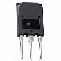
IRGPS40B120UPBF International Rectifier, IRGPS40B120UPBF Datasheet

IGBT ULT FAST 1200V 80A SUPER247

IRGPS40B120UPBF

Manufacturer Part Number
IRGPS40B120UPBF
Description
IGBT ULT FAST 1200V 80A SUPER247
Manufacturer
International Rectifier
Datasheet

Specifications of IRGPS40B120UPBF

Igbt Type
NPT
Voltage - Collector Emitter Breakdown (max)
1200V
Vce(on) (max) @ Vge, Ic
3.71V @ 15V, 50A
Current - Collector (ic) (max)
80A
Power - Max
595W
Input Type
Standard
Mounting Type
Through Hole
Package / Case
Super-247-3 (Straight Leads)
Channel Type
N
Configuration
Single
Collector-emitter Voltage
1.2kV
Collector Current (dc) (max)
80A
Gate To Emitter Voltage (max)
±20V
Pin Count
3 +Tab
Mounting
Through Hole
Operating Temperature (min)
-55
Operating Temperature (max)
150C
Operating Temperature Classification
Military
Transistor Type
IGBT
Dc Collector Current
80A
Collector Emitter Voltage Vces
3.5V
Power Dissipation Pd
595W
Collector Emitter Voltage V(br)ceo
1.2kV
Transistor Case Style
TO-274AA
No. Of Pins
3
Rohs Compliant
Yes
Operating Temperature Range
-55°C To +150°C
Lead Free Status / RoHS Status
Lead free / RoHS Compliant
Other names
*IRGPS40B120UPBF

Available stocks

Company
Part Number
Manufacturer
Quantity
Price
Part Number:
IRGPS40B120UPBF
Quantity:
49
Features
Benefits
• Benchmark Efficiency for Motor Control.
• Rugged Transient Performance.
• Low EMI.
• Significantly Less Snubber Required
• Excellent Current Sharing in Parallel Operation.
Thermal Resistance
INSULATED GATE BIPOLAR TRANSISTOR
• Non Punch Through IGBT Technology.
• 10µs Short Circuit Capability.
• Square RBSOA.
• Positive VCE (on) Temperature Coefficient.
• Super-247 Package.
• Lead-Free
Absolute Maximum Ratings
R
R
R
Wt
Le
V
I
I
I
I
V
P
P
T
T
www.irf.com
C
C
CM
LM
STG
CES
GE
D
D
J
θJC
θCS
θJA
@ T
@ T
@ T
@ T
C
C
C
C
= 25°C
= 100°C
= 25°C
= 100°C
Junction-to-Case - IGBT
Case-to-Sink, flat, greased surface
Junction-to-Ambient, typical socket mount
Recommended Clip Force
Weight
Internal Emitter Inductance (5mm from package)
Collector-to-Emitter Voltage
Continuous Collector Current
Pulsed Collector Current
Clamped Inductive Load Current 
Gate-to-Emitter Voltage
Maximum Power Dissipation
Operating Junction and
Storage Temperature Range
Soldering Temperature, for 10 sec.
Parameter
Parameter
G
IRGPS40B120UP
n-channel
20 (2)
Min.
–––
–––
–––
–––
–––
300 (0.063 in. (1.6mm) from case)
E
C
-55 to +150
Super-247™
6.0 (0.21)
Max.
1200
± 20
160
160
595
238
Typ.
80
40
0.24
–––
–––
–––
13
V
I
CE
CE(on)
V
@ V
UltraFast IGBT
= 40A, Tj=25°C
CES
Max.
GE
typ. = 3.12V
0.20
–––
–––
–––
–––
40
= 1200V
= 15V,
03/15/05
Units
Units
N(kgf)
g (oz)
°C/W
W
nH
°C
V
A
V
1

Related parts for IRGPS40B120UPBF

IRGPS40B120UPBF Summary of contents

Page 1

INSULATED GATE BIPOLAR TRANSISTOR Features • Non Punch Through IGBT Technology. • 10µs Short Circuit Capability. • Square RBSOA. • Positive VCE (on) Temperature Coefficient. • Super-247 Package. • Lead-Free Benefits • Benchmark Efficiency for Motor Control. • Rugged Transient ...

Page 2

IRGPS40B120UP Electrical Characteristics @ T Parameter V Collector-to-Emitter Breakdown Voltage (BR)CES ∆V Temperature Coeff. of Breakdown Voltage /∆T (BR)CES J V Collector-to-Emitter Saturation Voltage CE(on) V Gate Threshold Voltage GE(th) ∆ ∆ Temperature Coeff. of Threshold Voltage ...

Page 3

T C (°C) Fig Maximum DC Collector Current vs. Case Temperature 1000 100 0 100 V CE (V) ...

Page 4

IRGPS40B120UP 120 18V 100 VGE = 15V VGE = 12V VGE = 10V 80 VGE = 8. (V) Fig Typ. IGBT Output Characteristics T = ...

Page 5

V GE (V) Fig Typical -40° www.irf.com IRGPS40B120UP 20 18 ...

Page 6

IRGPS40B120UP 4500 4000 3500 E ON 3000 E OFF 2500 2000 1500 1000 500 (A) Fig Typ. Energy Loss vs 125°C; L=200µ 4.7Ω ...

Page 7

V CE (V) Fig. 16- Typ. Capacitance vs 0V 1MHz 0.50 0.20 0.10 0.1 0.05 0.01 0.02 SINGLE PULSE ( THERMAL RESPONSE ...

Page 8

IRGPS40B120UP DUT 0 1K Fig.C.T.1 - Gate Charge Circuit (turn-on) DRIVER DC DUT Fig.C.T.3 - S.C. SOA Circuit VCC DIODE CLAMP 900V DUT Rg Fig.C.T.5 - Resistive Load Circuit L ...

Page 9

Fig. WF.1 - Typ. Turn-off Loss Waveform @ Tj=125°C using Fig. CT.4 1100 1000 900 800 90% I 700 CE 600 tf 500 400 300 200 100 0 Eoff Loss -100 -0.20 0.00 0.20 ...

Page 10

... Super-247 (TO-274AA) Part Marking Information EXAMPLE: THIS IS AN IRFPS37N50A WITH ASSEMBLY LOT CODE 1789 ASSEMBLED ON WW 19, 1997 IN THE ASSEMBLY LINE "C" INTERNATIONAL RECTIFIER LOGO ASSEMBLY LOT CODE Note: "P" in assembly line position indicates "Lead-Free" IR WORLD HEADQUARTERS: 233 Kansas St., El Segundo, California 90245, USA Tel: (310) 252-7105 ...

Related keywords