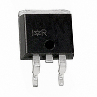
IRG4BC20K-SPBF International Rectifier, IRG4BC20K-SPBF Datasheet

IRG4BC20K-SPBF
Specifications of IRG4BC20K-SPBF
Related parts for IRG4BC20K-SPBF
IRG4BC20K-SPBF Summary of contents
Page 1
... Features www.irf.com IRG4BC20K-SPbF J G n-channel ‚ ƒ † C CES = CE(on) typ Pak 1 ...
Page 2
D (BR)CES † „ … www.irf.com ...
Page 3
Square wave: 60% of rated voltage 2.0 1.0 Ideal diodes 0.0 0.1 100 20µs PULSE WIDTH Collector-to-Emitter Voltage (V) CE www.irf.com For both: Duty ...
Page 4
T , Case Temperature ( 0.50 1 0.20 0.10 0.05 0.1 0.02 0.01 SINGLE PULSE (THERMAL RESPONSE) 0.01 0.00001 0.0001 4 5 15V GE 80 ...
Page 5
1MHz ies res oes ce gc 600 C ies 400 200 C oes C res 0 ...
Page 6
R = Ohm 150 C ° 480V 15V 4.0 GE 3.0 2.0 1.0 0 Collector-to-emitter Current ( 100 V = 20V ...
Page 7
L 50V 1000V * Driver same type as D.U.T 80% of Vce(max) * Note: Due to the 50V power supply, pulse width and inductor will increase to obtain rated Id. 50V 1000V Ã 10 ...
Page 8
Dimensions are shown in millimeters (inches ...
Page 9
Dimensions are shown in millimeters (inches) TRR FEED DIRECTION TRL FEED DIRECTION 330.00 (14.173) MAX. NOTES : 1. COMFORMS TO EIA-418. 2. CONTROLLING DIMENSION: MILLIMETER. 3. DIMENSION MEASURED @ HUB. 4. INCLUDES FLANGE DISTORTION @ OUTER EDGE. IR WORLD ...
Page 10
Note: For the most current drawings please refer to the IR website at: http://www.irf.com/package/ ...


