IXGH20N60B IXYS, IXGH20N60B Datasheet

IGBT 40A 600V TO-247AD

IXGH20N60B

Manufacturer Part Number
IXGH20N60B
Description
IGBT 40A 600V TO-247AD
Manufacturer
IXYS
Series
HiPerFAST™r
Datasheet

Specifications of IXGH20N60B

Voltage - Collector Emitter Breakdown (max)
600V
Vce(on) (max) @ Vge, Ic
2V @ 15V, 20A
Current - Collector (ic) (max)
40A
Power - Max
150W
Input Type
Standard
Mounting Type
Through Hole
Package / Case
TO-247AD
Channel Type
N
Configuration
Single
Collector-emitter Voltage
600V
Collector Current (dc) (max)
40A
Gate To Emitter Voltage (max)
±20V
Package Type
TO-247AD
Pin Count
3 +Tab
Mounting
Through Hole
Operating Temperature (min)
-55
Operating Temperature (max)
150C
Operating Temperature Classification
Military
Vces, (v)
600
Ic25, Tc=25°c, Igbt, (a)
40
Ic90, Tc=90°c, Igbt, (a)
20
Ic110, Tc=110°c, Igbt, (a)
-
Vce(sat), Max, Tj=25°c, Igbt, (v)
1.7
Tfi, Typ, Tj=25°c, Igbt, (ns)
100
Eoff, Typ, Tj=125°c, Igbt, (mj)
1.2
Rthjc, Max, Igbt, (°c/w)
0.83
If, Tj=110°c, Diode, (a)
-
Rthjc, Max, Diode, (ºc/w)
-
Package Style
TO-247
Lead Free Status / RoHS Status
Lead free / RoHS Compliant
Igbt Type
-
Lead Free Status / RoHS Status
Compliant, Lead free / RoHS Compliant

Available stocks

Company
Part Number
Manufacturer
Quantity
Price
Part Number:
IXGH20N60B
Manufacturer:
IXYS
Quantity:
15 500
Part Number:
IXGH20N60BD1
Manufacturer:
IXYS
Quantity:
15 500
Part Number:
IXGH20N60BU1
Manufacturer:
SANYO
Quantity:
673
Symbol
BV
V
I
I
V
© 2000 IXYS All rights reserved
HiPerFAST
Preliminary data sheet
IXYS reserves the right to change limits, test conditions, and dimensions.
Symbol
V
V
V
V
I
I
I
SSOA
(RBSOA)
P
T
T
T
Maximum Lead and Tab temperature for soldering
1.6 mm (0.062 in.) from case for 10 s
M
Weight
CES
GES
CM
C25
C90
GE(th)
CE(sat)
J
JM
stg
CES
CGR
GES
GEM
C
d
CES
Test Conditions
I
I
V
V
V
I
Test Conditions
T
T
Continuous
Transient
T
T
T
V
Clamped inductive load, L = 100 mH
T
Mounting torque, TO-247 AD
C
C
C
CE
GE
CE
C
C
C
C
J
J
GE
= 25°C to 150°C
= 25°C to 150°C; R
= 25°C
= 90°C
= 25°C, 1 ms
= 15 V, T
= 25°C
= 250mA, V
= 250 mA, V
= 0.8 • V
= 0 V
= 0 V, V
= I
C90
, V
TM
GE
GE
VJ
CES
= 15 V
= 125°C, R
= ±20 V
GE
CE
IGBT
= 0 V
= V
GE
GE
= 1 MW
G
= 22 W
T
T
J
J
(T
= 125°C
= 25°C
J
= 25°C, unless otherwise specified)
TO-247
TO-268
IXGH 20N60B
IXGT 20N60B
min.
600
2.5
Characteristic Values
-55 ... +150
-55 ... +150
@ 0.8 V
Maximum Ratings
typ.
I
1.7
1.13/10 Nm/lb.in.
CM
= 40
600
600
±20
±30
150
150
300
CES
40
20
80
max.
6
4
±100
200
5.0
2.0
1
mA
mA
nA
V
V
V
°C
°C
°C
°C
W
V
V
V
V
A
A
A
A
g
g
TO-268 (D3) (IXGT)
TO-247 AD (IXGH)
G = Gate,
E = Emitter,
Features
• International standard packages
• High current handling capability
• Latest generation HDMOS
• MOS Gate turn-on
Applications
• AC motor speed control
• DC servo and robot drives
• DC choppers
• Uninterruptible power supplies (UPS)
• Switched-mode and resonant-mode
Advantages
• Space savings (two devices in one
• High power density
• Suitable for surface mounting
• Switching speed for high frequency
• Easy to mount with 1 screw,TO-247
JEDEC TO-268 surface
mountable and JEDEC TO-247 AD
- drive simplicity
power supplies
package)
applications
(isolated mounting screw hole)
V
I
V
t
C25
fi(typ)
CES
CE(sat)typ
G
C
E
G
C = Collector,
TAB = Collector
E
= 600 V
=
= 1.7 V
= 100 ns
40 A
96533B (7/99)
TM
C (TAB)
process
(TAB)
1 - 4

Related parts for IXGH20N60B

IXGH20N60B Summary of contents

Page 1

... V = 0.8 • V CES CE CES ± GES CE(sat) C C90 GE IXYS reserves the right to change limits, test conditions, and dimensions. © 2000 IXYS All rights reserved IXGH 20N60B IXGT 20N60B Maximum Ratings 600 = 1 MW 600 GE ±20 ± 0.8 V CES 150 -55 ... +150 150 -55 ... +150 300 1 ...

Page 2

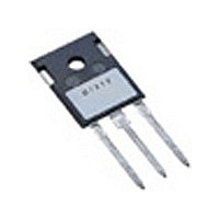
... L2 1.00 1.15 .039 .045 L3 0.25 BSC .010 BSC L4 3.80 4.10 .150 .161 IXYS MOSFETS and IGBTs are covered by one or more of the following U.S. patents: 4,835,592 4,881,106 5,017,508 4,850,072 4,931,844 5,034,796 IXGH 20N60B IXGT 20N60B TO-247 AD (IXGH) Outline ...

Page 3

... 125° Volts CE Fig. 3. High Temperature Output Characteristics 100 V = 10V 125° 25° Volts GE Fig. 5. Admittance Curves © 2000 IXYS All rights reserved 13V 11V 15V 13V 11V IXGH 20N60B IXGT 20N60B 200 T = 25° 160 120 Volts CE Fig. 2. Extended Output Characteristics 1 ...

Page 4

... nanocoulombs g Fig. 9. Gate Charge 1 D=0.5 D=0.2 0.1 D=0.1 D=0.05 D=0.02 D=0.01 0.01 Single pulse 0.001 0.00001 0.0001 Fig. 11. IGBT Transient Thermal Resistance Junction-to-Case © 2000 IXYS All rights reserved Fig. 8. Dependence of E OFF C 100 0.1 80 100 0 Fig. 10. Turn-off Safe Operating Area ...

Related keywords