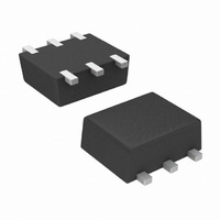
SI1029X-T1-E3 Vishay, SI1029X-T1-E3 Datasheet - Page 8

SI1029X-T1-E3
Manufacturer Part Number
SI1029X-T1-E3
Description
MOSFET N/P-CH COMPL 60V SOT563F
Manufacturer
Vishay
Series
TrenchFET®r
Specifications of SI1029X-T1-E3
Fet Type
N and P-Channel
Fet Feature
Logic Level Gate
Rds On (max) @ Id, Vgs
3 Ohm @ 200mA, 4.5V
Drain To Source Voltage (vdss)
60V
Current - Continuous Drain (id) @ 25° C
305mA, 190mA
Vgs(th) (max) @ Id
2.5V @ 250µA
Gate Charge (qg) @ Vgs
0.75nC @ 4.5V
Input Capacitance (ciss) @ Vds
30pF @ 25V
Power - Max
250mW
Mounting Type
Surface Mount
Package / Case
SC-89-6, SOT-563F, SOT-666
Module Configuration
Dual
Transistor Polarity
N And P Channel
Continuous Drain Current Id
500mA
Drain Source Voltage Vds
60V
On Resistance Rds(on)
1.4ohm
Rds(on) Test Voltage Vgs
10V
Lead Free Status / RoHS Status
Lead free / RoHS Compliant
Other names
SI1029X-T1-E3TR
Available stocks
Company
Part Number
Manufacturer
Quantity
Price
Document Number: 71612
25-Jun-01
4
NOTES:
1.
2.
2
3.
3
4.
5.
5
6.
6
Dimensions in millimeters.
Dimension D does not include mold flash, protrusions or gate
burrs. Mold flush, protrusions or gate burrs shall not exceed
0.15 mm per dimension E1 does not include interlead flash or
protrusion, interlead flash or protrusion shall not exceed
0.15 mm per side.
Dimensions D and E1 are determined at the outmost extremes
of the plastic body exclusive of mold flash, the bar burrs, gate
burrs and interlead flash, but including any mismatch between
the top and the bottom of the plastic body.
Datums A, B and D to be determined 0.10 mm from the lead tip.
Terminal numbers are shown for reference only.
These dimensions apply to the flat section of the lead between
0.08 mm and 0.15 mm from the lead tip.
2
2X
3
aaa
E1
L
C
A
L1
4
A
5
e
Î Î Î Î
Î Î
Î Î
Î Î
Î Î
Î Î
Î Î
Î Î
Î Î
Î Î
Î Î
Î Î
B
4
6
1
Î Î Î Î
Î Î
Î Î
Î Î
Î Î
Î Î
Î Î
Î Î
Î Î
Î Î
Î Î
Î Î
2
e1
D
3
5
2
Î Î Î Î
Î Î
Î Î
Î Î
Î Î
Î Î
Î Î
Î Î
Î Î
Î Î
Î Î
Î Î
6X b
4
3
ccc
2X
M
E/2
aaa
C
C
4
D
A–B D
ECN: E-00499—Rev. B, 02-Jul-01
DWG: 5880
E
Dim
A1
E1
e1
L1
A
D
E
b
c
e
L
2X
bbb
Min
0.56
0.00
0.15
0.10
1.50
1.55
C
A1
1.20 BSC
0.50 BSC
1.00 BSC
0.35 BSC
0.20 BSC
A1
Max
SEE DETAIL “A”
0.60
0.10
0.30
0.18
1.70
1.70
Î Î Î Î Î
Î Î Î Î Î
Î Î Î Î Î
Package Information
Note
2, 3
2, 3
DETAIL “A”
B
Symbol
Vishay Siliconix
aaa
bbb
ccc
C
SECTION B-B
6
Of Form And
Tolerances
Position
www.vishay.com
0.10
0.10
0.10
1


