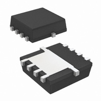
SI7403BDN-T1-E3 Vishay, SI7403BDN-T1-E3 Datasheet - Page 2

SI7403BDN-T1-E3
Manufacturer Part Number
SI7403BDN-T1-E3
Description
MOSFET P-CH 20V 8A 1212-8
Manufacturer
Vishay
Series
TrenchFET®r
Specifications of SI7403BDN-T1-E3
Fet Type
MOSFET P-Channel, Metal Oxide
Fet Feature
Logic Level Gate
Rds On (max) @ Id, Vgs
74 mOhm @ 5.1A, 4.5V
Drain To Source Voltage (vdss)
20V
Current - Continuous Drain (id) @ 25° C
8A
Vgs(th) (max) @ Id
1V @ 250µA
Gate Charge (qg) @ Vgs
15nC @ 8V
Input Capacitance (ciss) @ Vds
430pF @ 10V
Power - Max
9.6W
Mounting Type
Surface Mount
Package / Case
PowerPAK® 1212-8
Transistor Polarity
P Channel
Continuous Drain Current Id
-8A
Drain Source Voltage Vds
-20V
On Resistance Rds(on)
110mohm
Rds(on) Test Voltage Vgs
8V
Threshold Voltage Vgs Typ
-770mV
Configuration
Single Quad Drain Triple Source
Resistance Drain-source Rds (on)
0.074 Ohms
Drain-source Breakdown Voltage
- 20 V
Gate-source Breakdown Voltage
+/- 8 V
Continuous Drain Current
5.1 A
Power Dissipation
3.1 W
Maximum Operating Temperature
+ 150 C
Mounting Style
SMD/SMT
Minimum Operating Temperature
- 55 C
Lead Free Status / RoHS Status
Lead free / RoHS Compliant
Lead Free Status / RoHS Status
Lead free / RoHS Compliant, Lead free / RoHS Compliant
Other names
SI7403BDN-T1-E3TR
Available stocks
Company
Part Number
Manufacturer
Quantity
Price
Company:
Part Number:
SI7403BDN-T1-E3
Manufacturer:
LTC
Quantity:
187
Si7403BDN
Vishay Siliconix
Notes:
a. Surface Mounted on 1" x 1" FR4 board.
b. Maximum under Steady State conditions is 81 °C/W.
www.vishay.com
2
THERMAL RESISTANCE RATINGS
Parameter
Maximum Junction-to-Ambient
Maximum Junction-to-Case (Drain)
SPECIFICATIONS T
Parameter
Static
Drain-Source Breakdown Voltage
V
V
Gate-Source Threshold Voltage
Gate-Source Leakage
Zero Gate Voltage Drain Current
On-State Drain Current
Drain-Source On-State Resistance
Forward Transconductance
Dynamic
Input Capacitance
Output Capacitance
Reverse Transfer Capacitance
Total Gate Charge
Gate-Source Charge
Gate-Drain Charge
Gate Resistance
Turn-On Delay Time
Rise Time
Turn-Off Delay Time
Fall Time
Turn-On Delay Time
Rise Time
Turn-Off Delay Time
Fall Time
DS
GS(th)
Temperature Coefficient
Temperature Coefficient
b
a
a
J
a, b
= 25 °C, unless otherwise noted
a
ΔV
Symbol
ΔV
R
V
GS(th)
I
t
t
t
t
I
C
V
I
DS(on)
C
GS(th)
D(on)
C
Q
Q
d(on)
d(off)
d(on)
d(off)
GSS
DSS
DS
Q
g
R
oss
t
t
t
t
DS
rss
iss
fs
gs
gd
r
f
r
f
g
g
/T
/T
J
J
V
Steady State
V
I
DS
D
V
I
V
DS
D
DS
≅ - 4.1 A, V
t ≤ 10 s
DS
≅ - 4.1 A, V
= - 10 V, V
= - 10 V, V
= - 20 V, V
V
V
V
V
= - 10 V, V
V
V
V
V
V
V
V
DS
DS
GS
GS
DS
DD
DD
GS
DS
DS
DS
Test Conditions
≤ - 5 V, V
= V
= - 4.5 V, I
= - 2.5 V, I
= - 10 V, I
= - 10 V, R
= - 10 V, R
= 0 V, I
= - 20 V, V
= V
I
= 0 V, V
D
f = 1 MHz
GS
GEN
GS
= - 250 µA
GEN
GS
GS
GS
GS
, I
= - 4.5 V, I
, I
D
= - 8 V, I
D
= - 4.5 V, R
= 0 V, T
D
GS
= 0 V, f = 1 MHz
= - 8 V, R
GS
Symbol
= - 250 µA
= - 250 µA
D
D
D
R
= - 5 mA
R
GS
L
L
= - 5.1 A
= - 4.5 V
= - 5.1 A
= - 4.2 A
thJA
thJC
= - 8 V
= 2.4 Ω
= 2.4 Ω
= 0 V
D
J
D
= 55 °C
= - 5.1 A
g
= - 5.1 A
g
= 1 Ω
= 1 Ω
Typical
32
11
- 0.45
Min.
- 20
- 20
- 0.77
Maximum
0.059
0.080
Typ.
0.95
430
9.7
5.6
1.4
14
- 2
10
85
55
10
51
33
60
40
30
40
5
4
S-83051-Rev. B, 29-Dec-08
40
13
Document Number: 73333
0.074
0.110
Max.
- 100
- 1.0
- 10
8.5
- 1
15
10
75
50
90
60
45
60
8
°C/W
Unit
mV/°C
Unit
nA
µA
pF
nC
ns
Ω
Ω
V
V
A
S


