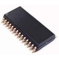
CS4272-DZZR Cirrus Logic Inc, CS4272-DZZR Datasheet - Page 24

CS4272-DZZR
Manufacturer Part Number
CS4272-DZZR
Description
Audio CODECs IC 24Bit 192kHz 114dB Str Codec
Manufacturer
Cirrus Logic Inc
Datasheet
1.CS4272-CZZ.pdf
(53 pages)
Specifications of CS4272-DZZR
Number Of Adc Inputs
2
Number Of Dac Outputs
2
Conversion Rate
192 KSPs
Interface Type
Serial (I2S, SPI)
Resolution
24 bit
Maximum Operating Temperature
+ 85 C
Mounting Style
SMD/SMT
Package / Case
TSSOP-28
Minimum Operating Temperature
- 40 C
Number Of Channels
2 ADC, 2 DAC
Lead Free Status / RoHS Status
Lead free / RoHS Compliant
Available stocks
Company
Part Number
Manufacturer
Quantity
Price
Company:
Part Number:
CS4272-DZZR
Manufacturer:
TI
Quantity:
12
5. APPLICATIONS
5.1
5.1.1
1) When using the CS4272 with an external MCLK, hold RST low until the power supply, MCLK, and LRCK are
2) Bring RST high. If the internally generated MCLK is being used, it will appear on the MCLK pin prior to 1 ms from
5.1.2
The CS4272 supports operation in either Master Mode or Slave Mode.
In Master Mode, LRCK and SCLK are outputs and are synchronously generated on-chip. LRCK is equal to Fs and
SCLK is equal to 64x Fs.
In Slave Mode, LRCK and SCLK are inputs, requiring external generation that is synchronous to MCLK. It is recom-
mended that SCLK be 64x Fs to maximize system performance.
In Stand-Alone Mode, the CS4272 will default to Slave Mode. Master Mode may be accessed by placing a 47 kΩ
pull-up to VL on the SDOUT (M/S) pin.
Configuration of clock ratios in each of these modes will be outlined in the Tables 3 and 4.
5.1.3
The CS4272 will operate at sampling frequencies from 4 kHz to 200 kHz. This range is divided into three speed
modes as shown in Table 1 below.
5.1.3.1
An external crystal may be used in conjunction with the CS4272 to generate the master clock signal. To accomplish
this, a 20 pF fundamental mode parallel resonant crystal must be connected between the XTI and XTO pins as
shown in the Typical Connection Diagram on page 23. This crystal must oscillate at the frequency shown in Table 2.
In this configuration, MCLK is a buffered output and, as shown in the Typical Connection Diagram, nothing other
than the crystal and its load capacitors should be connected to XTI and XTO. The MCLK signal will appear on the
MCLK pin prior to 1 ms from the release of RST.
To operate the CS4272 with an externally generated MCLK signal, no crystal should be used, XTI should be con-
nected to ground and XTO should be left unconnected. In this configuration, MCLK is an input and must be driven
externally with an appropriate speed clock.
24
stable. When using the CS4272 with internally generated MCLK, hold RST low until the power supply is stable.
the release of RST.
Stand-Alone Mode
Recommended Power-Up Sequence
Master/Slave Mode
System Clocking
Crystal Applications (XTI/XTO)
Double Speed
Double Speed
Single Speed
Single Speed
Quad Speed
Quad Speed
Mode
Mode
Table 2. Crystal Frequencies
Table 1. Speed Modes
Sampling Frequency
Crystal Frequency
100-200 kHz
50-100 kHz
512 x Fs
256 x Fs
128 x Fs
4-50 kHz
CS4272
DS593F1


