CUB5COM1 Red Lion Controls, CUB5COM1 Datasheet - Page 4
CUB5COM1
Manufacturer Part Number
CUB5COM1
Description
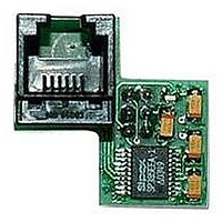
RS485 Serial Communications Card
Manufacturer
Red Lion Controls
Specifications of CUB5COM1
Accessory Type
RS485 Serial Communications Card
Brand/series
CUB5COM Series
Card Type
RS485 Serial Communications
Data Rate
300 to 19.2 K
Standards
UL Listed, IEC Certified
For Use With
Red Lion CUB5 Miniature Electronic 8-Digit Dual Counters And Rate Indicators
Lead Free Status / RoHS Status
Lead free / RoHS Compliant


Red Lion Controls
20 Willow Springs Circle
York PA 17402
Tel +1 (717) 767-6511
Fax +1 (717) 764-0839
Command Response Time
operation). During RS232 transmissions, the meter ignores commands while
transmitting data, but instead uses RXD as a busy signal. When sending
commands and data to the meter, a delay must be imposed before sending
another command. This allows enough time for the meter to process the
command and prepare for the next command.
string to the com port, thus initiating a transmission. During t
characters are under transmission and at the end of this period, the command
terminating character (* or $) is received by the meter. The time duration of t
is dependent on the number of characters and baud rate of the channel.
command and when complete, performs the command function. This time
interval t
to accept another command.
of the command terminating character. The ‘*’ terminating character results in
a response time of 50 msec. minimum. This allows sufficient time for the
release of the sending driver on the RS485 bus. Terminating the command line
with ‘$’ results in a response time (t
time of this terminating character requires that sending drivers release within 2
msec. after the terminating character is received.
Communication Format
In serial communications, the voltage is switched between a high and low level
at a predetermined rate (baud rate) using ASCII encoding. The receiving device
reads the voltage levels at the same intervals and then translates the switched
levels back to a character. The voltage level conventions depend on the interface
standard. The table lists the voltage levels for each standard.
characters (0 to
an optional parity bit and one or more ending stop bits. The data format and
baud rate must match that of other equipment in order for communication to
take place. The figures list the data formats employed by the meter.
The meter can only receive data or transmit data at any one time (half-duplex
At the start of the time interval t
At the start of time interval t
If the meter is to reply with data, the time interval t
Data is transferred from the meter through a serial communication channel.
Data is transmitted one byte at a time with a variable idle period between
* Voltage levels at the Receiver
LOGIC
1
0
2
varies. If no response from the meter is expected, the meter is ready
t
1
INTERFACE STATE
= (10 times the # of characters) / baud rate
space (active)
). Each ASCII character is “framed” with a beginning start bit,
mark (idle)
Character Frame Figure
2
1
, the meter starts the interpretation of the
2
TXD,RXD; +3 to +15 V
, the computer program prints or writes the
TXD,RXD; -3 to -15 V
) of 2 msec. minimum. The faster response
RS232*
2
is controlled by the use
a-b > +200 mV
a-b < -200 mV
1
, the command
RS485*
Fax +31 (0) 334 893 793
NL - 3821 BR Amersfoort
Tel +31 (0) 334 723 225
Red Lion Controls BV
Basicweg 11b
1
character of the reply. As with t
number of characters and baud rate of the channel. At the end of t
ready to receive the next command.
times t
Start Bit and Data Bits
receiving device to prepare for reception of data. One bit period later, the least
significant bit of the ASCII encoded character is transmitted, followed by the
remaining data bits. The receiving device then reads each bit position as they are
transmitted.
Parity Bit
a zero or a one, so that the total number of ones contained in the transmission
(including the parity bit) is either even or odd. This bit is used by the receiver
to detect errors that may occur to an odd number of bits in the transmission.
However, a single parity bit cannot detect errors that may occur to an even
number of bits. Given this limitation, the parity bit is often ignored by the
receiving device. The CUB5 meter ignores the parity bit of incoming data and
sets the parity bit to odd, even or none (mark parity) for outgoing data.
Stop Bit
period pause to allow the receiver to prepare to re-synchronize to the start of a
new transmission (start bit of next byte). The receiver then continuously looks
for the occurrence of the start bit. If 7 data bits and no parity is selected, then 2
stop bits are sent from the meter.
At the beginning of time interval t
The maximum serial throughput of the meter is limited to the sum of the
Data transmission always begins with the start bit. The start bit signals the
After the data bits, the parity bit is sent. The transmitter sets the parity bit to
The last character transmitted is the stop bit. The stop bit provides a single bit
1
, t
2
and t
t
3
= (10 times the # of characters) / baud rate
3
.
Timing Diagram Figure
1
, the time duration of t
3
, the meter responds with the first
3
31, Kaki Bukit Road 3,
is dependent on the
Red Lion Controls AP
#06-04/05 TechLink
Fax +65 6743-3360
Tel +65 6744-6613
Singapore 417818
3
, the meter is
Related parts for CUB5COM1
Image
Part Number
Description
Manufacturer
Datasheet
Request
R

Part Number:
Description:
Counter
Manufacturer:
Red Lion Controls
Datasheet:
Part Number:
Description:
Miniature Length Sensor
Manufacturer:
Red Lion Controls
Datasheet:
Part Number:
Description:
Model Lsc - Single Channel Output Length Sensor
Manufacturer:
Red Lion Controls
Datasheet: