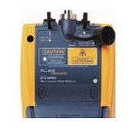
DTX-MFM2 FLUKE NETWORKS, DTX-MFM2 Datasheet - Page 38

DTX-MFM2
Manufacturer Part Number
DTX-MFM2
Description
DTX-MFM2 REPLACEMENT FOR DTX-MFM
Manufacturer
FLUKE NETWORKS
Datasheet
1.DTX-MFM2.pdf
(74 pages)
Specifications of DTX-MFM2
Multimode Fiber Module Set
ROHS COMPLIANT
DTX-MFM2/GFM2/SFM2 Fiber Modules
Users Manual
32
Autotest in Loopback Mode: Make Sure Your Test Reference Cords are Good
5
6
7
8
If you disconnected the test reference cord from
the tester’s output, you must set the reference
again to ensure valid measurements.
Disconnect the test reference cord from the INPUT port
on the tester.
Make the connections shown in Figure 9.
Turn the rotary switch to AUTOTEST, then press
Press
more than these limits:
An overall result of PASS does not show that the
test reference cords are good. You must compare
the loss to the limits given here to make sure the
cords are good.
H
to see the test result. The result must be no
W
W
Caution
Caution
P
.
9
10 Save the test results to show that you used good test
Multimode test reference cord:
850 nm: 0.11 dB or less
1300 nm: 0.10 dB or less
(The limits are different because fiber has more loss at
850 nm than at 1300 nm.)
Singlemode test reference cord:
0.20 dB or less for 1310 nm and 1550 nm
If a result is more than the limit shown above, use the
procedure given in Appendix A to test the cords.
When you have good test reference cords, set the
reference and do these steps (5 through 9) again
before you test a fiber link.
reference cords to test the link.
Fluke Networks recommends that you use this
procedure to make sure your test reference cords
are good before you test each fiber link.
Note


