BUK7107-55AIE,118 NXP Semiconductors, BUK7107-55AIE,118 Datasheet
BUK7107-55AIE,118
Specifications of BUK7107-55AIE,118
BUK7107-55AIE /T3
BUK7107-55AIE /T3


Related parts for BUK7107-55AIE,118


BUK7107-55AIE,118 Summary of contents
Page 1
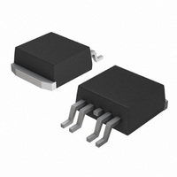
... Description N-channel enhancement mode field-effect power transistor in a plastic package using TrenchMOS™ technology, featuring very low on-state resistance, TrenchPLUS current sensing and diodes for ESD protection. Product availability: BUK7107-55AIE in SOT426 (D BUK7907-55AIE in SOT263B (TO-220AB). 1.2 Features Integrated current sensor ESD protection 1 ...
Page 2
Philips Semiconductors 3. Limiting values Table 2: Limiting values In accordance with the Absolute Maximum Rating System (IEC 60134). Symbol Parameter V drain-source voltage (DC drain-gate voltage (DC) DGS V gate-source voltage (DC drain current (DC) ...
Page 3
Philips Semiconductors 120 P der (%) 100 P tot P = ---------------------- - 100% der P tot 25 C Fig 1. Normalized total power dissipation as a function of mounting base temperature ...
Page 4
Philips Semiconductors 4. Thermal characteristics Table 3: Thermal characteristics Symbol Parameter R thermal resistance from junction to ambient th(j-a) SOT263B SOT426 R thermal resistance from junction to th(j-mb) mounting base 4.1 Transient thermal impedance ...
Page 5
Philips Semiconductors 5. Characteristics Table 4: Characteristics unless otherwise specified. j Symbol Parameter Static characteristics V drain-source breakdown (BR)DSS voltage V gate-source threshold voltage I GS(th) I drain-source leakage current DSS V gate-source breakdown (BR)GSS voltage ...
Page 6
Philips Semiconductors Table 4: Characteristics …continued unless otherwise specified. j Symbol Parameter Source-drain diode V source-drain (diode forward) SD voltage t reverse recovery time rr Q recovered charge r 9397 750 09877 Product data BUK71/7907-55AIE Conditions ...
Page 7
Philips Semiconductors 400 8.5 (A) 20 300 200 100 300 Fig 5. Output characteristics: drain current as a function of drain-source voltage; ...
Page 8
Philips Semiconductors 5 V GS(th) (V) 4 max 3 typ min - mA Fig 9. Gate-source threshold voltage as a function of junction temperature ...
Page 9
Philips Semiconductors 120 I D (A) 100 175 Fig 13. Transfer characteristics: drain current as a function of gate-source voltage; typical values. 600 sense ...
Page 10
Philips Semiconductors 6. Package outline Plastic single-ended surface mounted package (Philips version of D (one lead cropped DIMENSIONS (mm are the original dimensions UNIT b c 4.50 1.40 0.85 0.64 ...
Page 11
Philips Semiconductors Plastic single-ended package; heatsink mounted; 1 mounting hole; 5-lead TO-220 DIMENSIONS (mm are the original dimensions UNIT 4.5 1.39 0.85 0.7 15.8 mm 4.1 1.27 0.70 0.4 15.2 Notes ...
Page 12
Philips Semiconductors 7. Soldering handbook, full pagewidth 8.35 8.15 4.85 7.95 Dimensions in mm. Fig 19. Reflow soldering footprint for SOT426. 9397 750 09877 Product data 10.85 10.60 10.50 1.50 7.50 7.40 2.15 2.25 1.50 4.60 0.30 3.00 solder lands ...
Page 13
Philips Semiconductors 8. Revision history Table 5: Revision history Rev Date CPCN Description 01 20020812 - Product data; initial version 9397 750 09877 Product data BUK71/7907-55AIE Rev. 01 — 12 August 2002 TrenchPLUS standard level FET © Koninklijke Philips Electronics ...
Page 14
Philips Semiconductors Philips Semiconductors 9. Data sheet status [1] [2] Data sheet status Product status Objective data Development Preliminary data Qualification Product data Production [1] Please consult the most recently issued data sheet before initiating or completing a design. [2] ...
Page 15
Philips Semiconductors Contents 1 Product profi 1.1 Description . . . . . ...