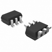
ATF-36163-TR2G Avago Technologies US Inc., ATF-36163-TR2G Datasheet

ATF-36163-TR2G
Specifications of ATF-36163-TR2G
Available stocks
Related parts for ATF-36163-TR2G
ATF-36163-TR2G Summary of contents
Page 1
... This feature makes the design of broad band low noise amplifiers much easier. The performance of the ATF-36163 makes this device the ideal choice for use in the 2nd or 3rd stage of low noise cascades. The repeatable performance ...
Page 2
... ATF-36163 Absolute Maximum Ratings Symbol Parameter V Drain - Source Voltage DS V Gate - Source Voltage GS V Gate Drain Voltage GD I Drain Current D P Total Power Dissipation Input Power in max T Channel Temperature CH T Storage Temperature STG ATF-36163 Electrical Specifications = 50 Ω 25° 1 Symbol Parameters and Test Conditions ...
Page 3
... Mag. Ang. - 0.78 28 0.38 0.75 41 0.32 0.68 55 0.26 0.60 71 0.20 0.55 88 0.15 0.48 105 0.12 Figure 1. ATF-36163 Minimum Noise Figure and 0.38 119 0.10 Associated Gain vs. Frequency for 0.32 138 0.07 V 0.23 170 0.07 0.18 -141 0.09 0.20 -92 0.13 0.26 -46 0.21 ...
Page 4
... O Mag. Ang. - 0.84 28 0.38 0.74 42 0.31 0.66 57 0.25 0.59 72 0.19 0.54 90 0.15 Figure 3. ATF-36163 Minimum Noise Figure and 0.46 106 0.11 Associated Gain vs. Frequency for V 0.37 121 0.09 0.30 140 0.08 0.21 174 0.08 0.17 -133 0.10 0.20 -83 0.14 ...
Page 5
... O Mag. Ang. - 0.84 28 0.38 0.76 41 0.31 0.67 56 0.25 0.61 70 0.20 0.55 88 0.15 0.49 103 0.12 Figure 5. ATF-36163 Minimum Noise Figure and 0.39 118 0.10 Associated Gain vs. Frequency for 0.33 135 0. 0.23 165 0.07 0.17 -145 0.09 0.18 -93 0.12 0.24 -47 0.19 0.34 -16 0 ...
Page 6
... FREQUENCY (GHz) Figure 7. ATF-36163 Minimum Noise Figure and Associated Gain vs. Frequency for mA MSG 12 MAG 2 |S21 FREQUENCY (GHz) Figure 8. Maximum Available Gain, Maximum Stable Gain & Insertion Power Gain vs. ...
Page 7
... ATF-36163 Typical “Off” Scattering Parameters, Freq GHz Mag. Ang. 0.5 0. 0.98 -16 2 0.99 -30 3 0.98 -43 4 0.97 -57 5 0.96 -72 6 0.94 -87 7 0.92 -103 8 0.89 -119 9 0 ...
Page 8
... Figure 10. Reference Planes mA. D SOT-363 PCB Layout A PCB pad layout for the minia- ture SOT-363 (SC-70) package used by the ATF-36163 is shown in Figure 11 (dimensions are in inches). This layout provides ample allowance for package placement by automated assembly equipment. The layout is shown with a nominal SOT-363 package footprint superimposed on the PCB pads ...
Page 9
... Part Number Ordering Information No. of Part Number Devices ATF-36163-TR1 3000 ATF-36163-TR2 10000 ATF-36163-BLK 100 ATF-36163-TR1G 3000 ATF-36163-TR2G 10000 ATF-36163-BLKG 100 Note: For lead-free option, the part number will have the character “G” at the end NOTES: 1. All dimensions are in mm. ...
Page 10
Device Orientation REEL USER FEED DIRECTION COVER TAPE Tape Dimensions and Product Orientation For Outline DESCRIPTION CAVITY LENGTH WIDTH DEPTH PITCH BOTTOM HOLE DIAMETER PERFORATION DIAMETER PITCH POSITION CARRIER TAPE WIDTH THICKNESS COVER TAPE WIDTH ...
Page 11
For product information and a complete list of distributors, please go to our web site: www.avagotech.com Avago, Avago Technologies, and the A logo are trademarks of Avago Technologies, Pte. in the United States and other countries. Data subject to change. ...


