MRF6V2300NR1 Freescale Semiconductor, MRF6V2300NR1 Datasheet - Page 2
MRF6V2300NR1
Manufacturer Part Number
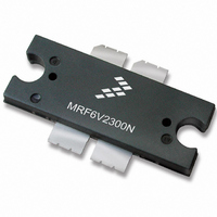
MRF6V2300NR1
Description
MOSFET RF N-CH TO-270-4
Manufacturer
Freescale Semiconductor
Datasheet
1.MRF6V2300NBR5.pdf
(19 pages)
Specifications of MRF6V2300NR1
Transistor Type
N-Channel
Frequency
220MHz
Gain
25.5dB
Voltage - Rated
110V
Current Rating
2.5mA
Current - Test
900mA
Voltage - Test
50V
Power - Output
300W
Package / Case
TO-270-4
Channel Type
N
Channel Mode
Enhancement
Drain Source Voltage (max)
110V
Output Power (max)
300W
Power Gain (typ)@vds
31.4dB
Frequency (min)
10MHz
Frequency (max)
600MHz
Package Type
TO-270 WB EP
Pin Count
5
Input Capacitance (typ)@vds
268@50VpF
Output Capacitance (typ)@vds
120@50VpF
Reverse Capacitance (typ)
2.88@50VpF
Operating Temp Range
-65C to 225C
Drain Efficiency (typ)
61.5%
Mounting
Surface Mount
Mode Of Operation
CW
Number Of Elements
1
Vswr (max)
10
Screening Level
Military
Lead Free Status / RoHS Status
Contains lead / RoHS non-compliant
Noise Figure
-
Lead Free Status / Rohs Status
Compliant
Available stocks
Company
Part Number
Manufacturer
Quantity
Price

Part Number:
MRF6V2300NR1
Manufacturer:
FREESCALE
Quantity:
20 000


2
MRF6V2300NR1 MRF6V2300NBR1
Table 4. Moisture Sensitivity Level
Table 5. Electrical Characteristics
Off Characteristics
On Characteristics
Dynamic Characteristics
Functional Tests (In Freescale Test Fixture, 50 ohm system) V
Typical Performances (In Freescale 27 MHz and 450 MHz Test Fixtures, 50 ohm system) V
Per JESD22--A113, IPC/JEDEC J--STD--020
Zero Gate Voltage Drain Leakage Current
Zero Gate Voltage Drain Leakage Current
Drain--Source Breakdown Voltage
Gate--Source Leakage Current
Gate Threshold Voltage
Gate Quiescent Voltage
Drain--Source On--Voltage
Reverse Transfer Capacitance
Output Capacitance
Input Capacitance
Power Gain
Drain Efficiency
Input Return Loss
Power Gain
Drain Efficiency
Input Return Loss
(V
(V
(I
(V
(V
(V
(V
(V
(V
(V
D
DS
DS
GS
DS
DD
GS
DS
DS
DS
= 150 mA, V
= 100 Vdc, V
= 50 Vdc, V
= 5 Vdc, V
= 10 Vdc, I
= 50 Vdc, I
= 10 Vdc, I
= 50 Vdc ± 30 mV(rms)ac @ 1 MHz, V
= 50 Vdc ± 30 mV(rms)ac @ 1 MHz, V
= 50 Vdc, V
GS
DS
D
D
D
GS
GS
= 800 μAdc)
= 900 mAdc, Measured in Functional Test)
= 2 Adc)
GS
= 0 Vdc)
= 0 Vdc)
= 0 Vdc)
= 0 Vdc ± 30 mV(rms)ac @ 1 MHz)
= 0 Vdc)
Test Methodology
ATTENTION: The MRF6V2300N and MRF6V2300NB are high power devices and special considerations
must be followed in board design and mounting. Incorrect mounting can lead to internal temperatures which
exceed the maximum allowable operating junction temperature. Refer to Freescale Application Note AN3263
(for bolt down mounting) or AN1907 (for solder reflow mounting) PRIOR TO STARTING SYSTEM DESIGN to
ensure proper mounting of these devices.
Characteristic
(T
A
f = 27 MHz
f = 450 MHz
f = 27 MHz
f = 450 MHz
f = 27 MHz
f = 450 MHz
= 25°C unless otherwise noted)
GS
GS
= 0 Vdc)
= 0 Vdc)
DD
= 50 Vdc, I
DQ
V
Symbol
V
Rating
V
V
(BR)DSS
I
I
I
C
DS(on)
C
GS(th)
GS(Q)
C
G
G
= 900 mA, P
IRL
IRL
DSS
DSS
GSS
η
η
3
oss
rss
iss
ps
ps
D
D
DD
out
Min
110
Package Peak Temperature
1.5
24
66
—
—
—
—
—
—
—
—
—
—
—
—
—
—
1
= 50 Vdc, I
= 300 W, f = 220 MHz, CW
--17.4
--24.4
DQ
1.63
0.28
2.88
25.5
31.4
21.7
61.5
59.1
260
Typ
120
268
--16
2.6
68
—
—
—
—
= 900 mA, P
Freescale Semiconductor
Max
2.5
3.5
50
10
27
—
—
—
—
—
—
--9
—
—
—
—
—
—
3
out
RF Device Data
= 300 W CW
μAdc
μAdc
Unit
Unit
Vdc
Vdc
Vdc
Vdc
mA
dB
dB
dB
dB
°C
pF
pF
pF
%
%
Related parts for MRF6V2300NR1
Image
Part Number
Description
Manufacturer
Datasheet
Request
R

Part Number:
Description:
Manufacturer:
Freescale Semiconductor, Inc
Datasheet:
Part Number:
Description:
Manufacturer:
Freescale Semiconductor, Inc
Datasheet:
Part Number:
Description:
Manufacturer:
Freescale Semiconductor, Inc
Datasheet:
Part Number:
Description:
Manufacturer:
Freescale Semiconductor, Inc
Datasheet:
Part Number:
Description:
Manufacturer:
Freescale Semiconductor, Inc
Datasheet:
Part Number:
Description:
Manufacturer:
Freescale Semiconductor, Inc
Datasheet:
Part Number:
Description:
Manufacturer:
Freescale Semiconductor, Inc
Datasheet:
Part Number:
Description:
Manufacturer:
Freescale Semiconductor, Inc
Datasheet:
Part Number:
Description:
Manufacturer:
Freescale Semiconductor, Inc
Datasheet:
Part Number:
Description:
Manufacturer:
Freescale Semiconductor, Inc
Datasheet:
Part Number:
Description:
Manufacturer:
Freescale Semiconductor, Inc
Datasheet:
Part Number:
Description:
Manufacturer:
Freescale Semiconductor, Inc
Datasheet:
Part Number:
Description:
Manufacturer:
Freescale Semiconductor, Inc
Datasheet:
Part Number:
Description:
Manufacturer:
Freescale Semiconductor, Inc
Datasheet:
Part Number:
Description:
Manufacturer:
Freescale Semiconductor, Inc
Datasheet: