SHF-0189 Sirenza Microdevices Inc, SHF-0189 Datasheet - Page 2
SHF-0189
Manufacturer Part Number
SHF-0189
Description
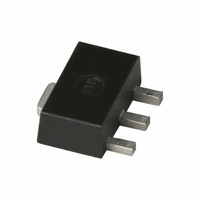
IC HFET ALGAAS/GAAS .5W SOT-89
Manufacturer
Sirenza Microdevices Inc
Datasheet
1.SHF-0189.pdf
(6 pages)
Specifications of SHF-0189
Transistor Type
HFET
Frequency
1.96GHz
Gain
20.1dB
Voltage - Rated
9V
Current Rating
200mA
Noise Figure
3.2dB
Current - Test
100mA
Voltage - Test
8V
Power - Output
27.5dBm
Package / Case
SOT-89
Lead Free Status / RoHS Status
Contains lead / RoHS non-compliant
Other names
599-1060-2
Available stocks
Company
Part Number
Manufacturer
Quantity
Price
Company:

Part Number:
SHF-0189
Manufacturer:
SIRENZA
Quantity:
51 000
Company:
Part Number:
SHF-0189
Manufacturer:
STANFORD
Quantity:
270
Company:
Part Number:
SHF-0189Z
Manufacturer:
SIRENZA
Quantity:
37 000
Company:
Part Number:
SHF-0189Z
Manufacturer:
RFMD21
Quantity:
6 979
Part Number:
SHF-0189Z
Manufacturer:
RFMD
Quantity:
20 000


SHF-0189(Z)
Typical Performance with Engineering Application Circuits
2 of 6
Absolute Maximum Ratings
Drain Current (I
Forward Gate Current (I
Reverse Gate Current (I
Drain-to-Source Voltage (V
Gate-to-Source Voltage (V
RF Input Power (P
Operating Lead Temperature (T
Storage Temperature Range (T
Power Dissipation (P
Channel Temperature (T
Moisture Sensitivity Level
Operation of this device beyond any one of these limits may cause permanent dam-
MTTF is inversely proportional to the device junction temperature. MTTF at
P
*P
DC
OUT
<(T
age. For reliable continuous operation, the device voltage and current must not
exceed the maximum operating values specified in the table on page one.
T
ture and MTTF considerations the bias condition should also satisfy the follow-
ing expressions:
Temperature (pin 4) (°C), R
J
=150°C exceeds 1E7 hours. For junction temperature. For junction tempera-
=+15dBm per tone, 1MHz tone spacing
J
1.50
1.25
1.00
0.75
0.50
0.25
0.00
- T
L
)/R
Parameter
-40
TH
DS
)
IN
where R
)
(MHz)
DISS
Freq
1960
2450
2140
900
-15
GSF
GSR
J
)
)
GS
DC
DS
)
)
)
)
=I
Operational (Tj<150C)
stor
ABS MAX (Tj<165C)
DS
L
TH
)
Lead Temperature (C)
*V
Power Derating Curve
10
)
=Thermal Resistance (°C/W)
DS
7628 Thorndike Road, Greensboro, NC 27409-9421 · For sales or technical
support, contact RFMD at (+1) 336-678-5570 or sales-support@rfmd.com.
(W), T
35
J
=Junction Temperature (°C), T
-40 to +150
See graph
See graph
<-5 or >0
Rating
MSL 2
VDS
+165
60
+9.0
200
200
(V)
1.2
1.2
8
8
8
8
85
(mA)
IDQ
100
100
100
100
110
L
Unit
=Lead
mA
mA
mA
mW
°C
°C
°C
(dBm)
W
V
P1dB
V
27.6
27.2
27.5
27.3
135
Exceeding any one or a combination of the Absolute Maximum Rating conditions may
cause permanent damage to the device. Extended application of Absolute Maximum
Rating conditions to the device may reduce device reliability. Specified typical perfor-
mance or functional operation of the device under Absolute Maximum Rating condi-
tions is not implied.
RoHS status based on EUDirective2002/95/EC (at time of this document revision).
The information in this publication is believed to be accurate and reliable. However, no
responsibility is assumed by RF Micro Devices, Inc. ("RFMD") for its use, nor for any
infringement of patents, or other rights of third parties, resulting from its use. No
license is granted by implication or otherwise under any patent or patent rights of
RFMD. RFMD reserves the right to change component circuitry, recommended appli-
cation circuitry and specifications at any time without prior notice.
160
OIP3*
(dBm)
40
40
40
40
Caution! ESD sensitive device.
Gain
(dB)
18.6
16.7
15.2
15.2
This area not recommended
for continuous reliable operation.
S11
(dB)
-25
-20
-24
-16
S22
(dB)
-13
-14
-14
EDS-101240 Rev G
-8
(dB)
NF
4.7
3.2
3.8
3.1
Related parts for SHF-0189
Image
Part Number
Description
Manufacturer
Datasheet
Request
R

Part Number:
Description:
IC HFET ALGAAS/GAAS 1W SOT-89
Manufacturer:
Sirenza Microdevices Inc
Datasheet:

Part Number:
Description:
IC HFET ALGAAS/GAAS 1W SOT-89
Manufacturer:
Sirenza Microdevices Inc
Datasheet:

Part Number:
Description:
Manufacturer:
Sirenza Microdevices Inc
Datasheet:
Part Number:
Description:
Manufacturer:
Sirenza Microdevices Inc
Datasheet:
Part Number:
Description:
Manufacturer:
Sirenza Microdevices Inc
Datasheet:

Part Number:
Description:
IC TRANSISTOR LDMOS 3W 2-SOIC
Manufacturer:
Sirenza Microdevices Inc
Datasheet:

Part Number:
Description:
IC AMP HBT SIGE 6GHZ SOT-343
Manufacturer:
Sirenza Microdevices Inc
Datasheet:
Part Number:
Description:
IC AMP HBT SIGE 5000MHZ SOT-363
Manufacturer:
Sirenza Microdevices Inc
Datasheet:
Part Number:
Description:
IC AMP HBT SIGE 5000MHZ SOT-363
Manufacturer:
Sirenza Microdevices Inc
Datasheet:
Part Number:
Description:
IC AMP HBT SIGE 3500MHZ SOT-363
Manufacturer:
Sirenza Microdevices Inc
Datasheet:
Part Number:
Description:
Manufacturer:
Sirenza Microdevices Inc
Datasheet:
Part Number:
Description:
Manufacturer:
Sirenza Microdevices Inc
Datasheet:
Part Number:
Description:
Manufacturer:
Sirenza Microdevices Inc
Datasheet:
Part Number:
Description:
IC AMP HBT GAAS 1/2W SOT-89
Manufacturer:
Sirenza Microdevices Inc
Datasheet:
Part Number:
Description:
IC AMP HBT 8000MHZ SOT-89
Manufacturer:
Sirenza Microdevices Inc
Datasheet: