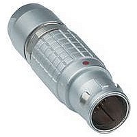
FGG.0B.304.CLAD52Z LEMO, FGG.0B.304.CLAD52Z Datasheet - Page 11

FGG.0B.304.CLAD52Z
Manufacturer Part Number
FGG.0B.304.CLAD52Z
Description
Conn Circular M 4 POS Solder ST Cable Mount 4 Terminal 1 Port
Manufacturer
LEMO
Type
Circularr
Series
Br
Datasheet
1.FGG.1B.304.CLAZ.pdf
(212 pages)
Specifications of FGG.0B.304.CLAD52Z
Gender
PL
Termination Method
Solder
Mounting
Cable Mount
Body Orientation
Straight
Connector Body Material
Brass
Contact Gender
Pin
Connector Mounting
Cable
Insert Arrangement
304
Connector Type
Circular Industrial
Lead Free Status / RoHS Status
- Current page: 11 of 212
- Download datasheet (6Mb)
Selection of contact types
Solder contacts
The conductor bucket of these contacts is machined at
an angle to form a cup into which the solder can flow.
Note:
1)
2)
3)
Crimp contacts
The crimp contacts are designed to be crimped with the
standard four indent method according to MIL-C-22520F,
class 1, type 1.
Note:
designs is larger than the solder cup diameter. Make sure that the
maximum conductor diameter is smaller than ø C.
A detailed range of conductor dimensions that can be
crimped into our contacts is given on the table at right.
See also the section on tooling (pages 183 to 188).
Print contacts
Print contacts are available in straight or elbow versions
for certain connector types. Connection is possible by
soldering on flexible or rigid printed circuit boards.
Straight print contacts are gold-plated which guarantees
Fig. 1
Fig. 2
straight
for S, E, 2C, 2G and 1D series
for 00 multipole series
for a given AWG, the diameter of some stranded conductor designs
is larger than the solder cup diameter. Make sure that the maximum
conductor diameter is smaller than ø C.
ø A
1)
for a given AWG, the diameter of some stranded conductor
ø A
ø A
ø A
ø A
L
ø A
ø A
ø C
ø A
ø C
ø C
ø C
ø C
ø C
ø C
L
ø C
Contacts are provided in two forms: with a standard crimp
barrel for large conductors (see fig. 1), or with a reduced
crimp barrel for smaller conductors (see fig. 2).
Note: Fr = mean contact retention force in the insulator (according to
IEC 60512-8 test 15a).
optimum soldering, even after longterm storage.
Print elbow contacts include a tinned copper wire crimped
into a contact. L dimensions and C ø are detailed in the
section on PCB drilling patterns.
(mm) (mm) per fig.
elbow
ø A
0.5
0.7
0.9
1.3
1.6
2.0
3.0
4.0
(mm)
12.0
ø A
0.5
0.5
0.7
0.7
0.9
1.3
1.6
2.0
3.0
4.0
5.0
6.0
8.0
Contact
Contact
2)
1)
0.45
0.80
0.45
1.10
0.80
0.45
1.40
1.10
0.80
1.90
1.40
2.40
1.90
2.90
4.00
ø C
(mm)
0.40
0.45
0.60
0.80
0.80
1.00
1.40
1.80
2.70
3.70
5.20
5.20
7.00
6.20
ø C
Form
1
1
2
1
2
2
1
2
2
1
2
1
2
1
1
2)
1)
ø A
AWG
max.
AWG stranded
28
28
24
22
22
20
16
14
10
10
min.
–
–
–
–
32
26
32
24
26
32
20
24
26
18
22
16
18
14
12
Solid
Conductor stranded
max (mm
max.
Section
28
22
28
20
22
28
18
20
22
14
18
12
14
10
10
0.09
0.09
0.25
0.34
0.34
0.50
1.00
1.50
4.00
6.00
1)
1)
1)
1)
1)
1)
–
–
–
–
Conductor
L
2
)
0.035
0.140
0.035
0.250
0.140
0.035
0.500
0.250
0.140
1.000
0.340
1.500
1.000
2.500
4.000
Section (mm
min.
AWG
max.
30
28
26
22
22
20
18
16
12
10
8
8
4
6
ø C
3)
3)
3)
max.
0.09
0.34
0.09
0.50
0.34
0.09
1.00
0.50
0.34
1.50
1.00
2.50
1.50
4.00
6.00
®
Stranded
2
)
max (mm
Section
10.00
10.00
16.00
16.00
0.05
0.09
0.14
0.34
0.34
0.50
1.00
1.50
4.00
6.00
(N)
12
22
30
40
50
65
75
90
F
r
2
)
9
®
Related parts for FGG.0B.304.CLAD52Z
Image
Part Number
Description
Manufacturer
Datasheet
Request
R

Part Number:
Description:
RF Connectors ADAPTOR SOCKET TO BNC PLUG
Manufacturer:
LEMO
Datasheet:

Part Number:
Description:
RF Connectors ADAPT-BNC(UG88U)COAX
Manufacturer:
LEMO
Datasheet:

Part Number:
Description:
RF Connectors BNC ADAPTER 50 OHM
Manufacturer:
LEMO
Datasheet:

Part Number:
Description:
LEMO, SPRING LOADED DUSTCAP
Manufacturer:
LEMO
Datasheet:

Part Number:
Description:
Circular Push Pull Connectors CONNECTOR WRENCH FOR LEMO
Manufacturer:
LEMO

Part Number:
Description:
Specifications: Connector Type: Plug, Male Pins ; Shell Size - Insert: 114 ; Mounting Type: Free Hanging (In-Line) ; Fastening Type: Threaded ; Features: Shielded ; Packaging: Bulk ; Number of Positions: 114 ; Termination: Crimp ; Shell Material, Fin
Manufacturer:
LEMO

Part Number:
Description:
Specifications: Connector Style: - ; Connector Type: Plug ; Simplex/Duplex: Duplex ; Mode: Singlemode ; Fiber Diameter: 125
Manufacturer:
LEMO


