FGG.0B.304.CLAD52Z LEMO, FGG.0B.304.CLAD52Z Datasheet - Page 206
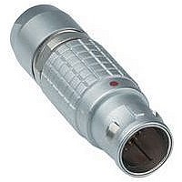
FGG.0B.304.CLAD52Z
Manufacturer Part Number
FGG.0B.304.CLAD52Z
Description
Conn Circular M 4 POS Solder ST Cable Mount 4 Terminal 1 Port
Manufacturer
LEMO
Type
Circularr
Series
Br
Datasheet
1.FGG.1B.304.CLAZ.pdf
(212 pages)
Specifications of FGG.0B.304.CLAD52Z
Gender
PL
Termination Method
Solder
Mounting
Cable Mount
Body Orientation
Straight
Connector Body Material
Brass
Contact Gender
Pin
Connector Mounting
Cable
Insert Arrangement
304
Connector Type
Circular Industrial
Lead Free Status / RoHS Status


Print contacts
Print contacts are available in straight or elbow versions
for certain connector types, mostly for straight and elbow soc-
ket models. Connection is made on flexible or rigid printed
circuits by soldering.
Straight print contacts are gold-plated which guarantees
optimum soldering, even after long-term storage. However
Test voltage
Test voltage (Ue) :
(measured according to the IEC 60512-2 test 4a standard)
It corresponds to 75% of the mean breakdown voltage.
Test voltage is applied at 500 V/s and the test duration is 1
minute.
This test has been carried out with a mated plug and soc-
ket, with power supply only on the plug end.
Operating voltage (Us) :
It is proposed according to the following ratio : Us =
Caution:
For a number of applications, safety requirements for
electrical appliances are more severe with regard to
operating voltage.
In such cases operating voltage is defined according
to creepage distance and air clearance) between live parts.
Please consult us for the choice of a connector by indi-
cating the safety standard to be met by the product.
Rated current
(measured according to IEC 60512-3 test 5a)
The specified rated current can be applied simultaneously
to all the contacts.
It corresponds with an average temperature rise of 40°C of
the connector.
The current values are indicated in the table of insulator
types in each series.
For use at higher temperatures acceptable rated current
will be lower. It tends towards zero as the material is used
at the maximum operating temperature accepted for the
insulator.
In most case the current depend on the conductor dimen-
sion (see table on page 210) or on the printed circuit dimen-
sion.
Caution:
In general, connectors should not be unmated while
live.
204
straight
®
®
Ue
3
for wave soldering, we recommend removal the gold-plating
from the contact end on the printed circuit side before sol-
dering according to the assembly procedures.
Print elbow contacts include a tinned brass wire crimped into
a crimp contact.
Voltage values are given in the table on insulator types for
each series.
They correspond with values measured at sea level.
They are adapted to all applications up to an altitude of
2000 m.
In case a device is used at a higher altitude, air clearance
between live parts has to be multiplied by the following
coefficients.
It means also that test voltage has to be divided by this
coefficient.
For connectors with PEEK insulator, maximum admissible
current will follow the curve below depending on the operating
temperature T.
elbow
100%
75%
50%
25%
altitude (m)
0
2000
3000
4000
5000
Rated current (A)
50
coefficient
1.00
1.14
1.29
1.48
100
150
200
250
T ( C)
Related parts for FGG.0B.304.CLAD52Z
Image
Part Number
Description
Manufacturer
Datasheet
Request
R

Part Number:
Description:
RF Connectors ADAPTOR SOCKET TO BNC PLUG
Manufacturer:
LEMO
Datasheet:

Part Number:
Description:
RF Connectors ADAPT-BNC(UG88U)COAX
Manufacturer:
LEMO
Datasheet:
Part Number:
Description:
RF Connectors BNC ADAPTER 50 OHM
Manufacturer:
LEMO
Datasheet:

Part Number:
Description:
LEMO, SPRING LOADED DUSTCAP
Manufacturer:
LEMO
Datasheet:

Part Number:
Description:
Circular Push Pull Connectors CONNECTOR WRENCH FOR LEMO
Manufacturer:
LEMO
Part Number:
Description:
Specifications: Connector Type: Plug, Male Pins ; Shell Size - Insert: 114 ; Mounting Type: Free Hanging (In-Line) ; Fastening Type: Threaded ; Features: Shielded ; Packaging: Bulk ; Number of Positions: 114 ; Termination: Crimp ; Shell Material, Fin
Manufacturer:
LEMO
Part Number:
Description:
Specifications: Connector Style: - ; Connector Type: Plug ; Simplex/Duplex: Duplex ; Mode: Singlemode ; Fiber Diameter: 125
Manufacturer:
LEMO