25RIA10 Vishay, 25RIA10 Datasheet - Page 4
25RIA10
Manufacturer Part Number
25RIA10
Description
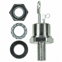
SCR MED POWER 100V 25A TO-48
Manufacturer
Vishay
Specifications of 25RIA10
Scr Type
Standard Recovery
Voltage - Off State
100V
Voltage - Gate Trigger (vgt) (max)
2V
Voltage - On State (vtm) (max)
1.7V
Current - On State (it (av)) (max)
25A
Current - On State (it (rms)) (max)
40A
Current - Gate Trigger (igt) (max)
60mA
Current - Hold (ih) (max)
130mA
Current - Off State (max)
20mA
Current - Non Rep. Surge 50, 60hz (itsm)
420A, 440A
Operating Temperature
-65°C ~ 125°C
Mounting Type
Chassis, Stud Mount
Package / Case
TO-208AA, TO-48
Current - On State (it (rms) (max)
40A
Breakover Current Ibo Max
440 A
Rated Repetitive Off-state Voltage Vdrm
100 V
Off-state Leakage Current @ Vdrm Idrm
20 mA
Forward Voltage Drop
1.7 V
Gate Trigger Voltage (vgt)
2 V
Maximum Gate Peak Inverse Voltage
10 V
Gate Trigger Current (igt)
60 mA
Holding Current (ih Max)
130 mA
Mounting Style
Stud
Peak Repetitive Off-state Voltage, Vdrm
1kV
Gate Trigger Current Max, Igt
60mA
Current It Av
40A
On State Rms Current It(rms)
40A
Peak Non Rep Surge Current Itsm 50hz
420A
Lead Free Status / RoHS Status
Lead free / RoHS Compliant
Other names
*25RIA10


25RIA Series
Vishay High Power Products
Note
• The table above shows the increment of thermal resistance R
www.vishay.com
4
THERMAL AND MECHANICAL SPECIFICATIONS
PARAMETER
Maximum operating junction
and storage temperature range
Maximum thermal resistance,
junction to case
Maximum thermal resistance,
case to heatsink
Allowable mounting torque
Approximate weight
Case style
ΔR
CONDUCTION ANGLE
thJC
CONDUCTION
180°
120°
130
120
110
100
90°
60°
30°
90
80
Fig. 1 - Current Ratings Characteristics
0
5
Average On-state Current (A)
30°
25RIA Series
R
10
thJC
60°
(DC) = 0.75 K/W
SINUSOIDAL CONDUCTION
15
90°
Conduction Angle
120°
For technical questions, contact: ind-modules@vishay.com
20
SYMBOL
T
180°
R
R
J
0.17
0.21
0.27
0.40
0.69
, T
25
thCS
thJC
Stg
Medium Power Thyristors
30
(Stud Version), 25 A
DC operation
Mounting surface, smooth, flat and greased
Non-lubricated threads
Lubricated threads
See dimensions - link at the end of datasheet
thJC
when devices operate at different conduction angles than DC
RECTANGULAR CONDUCTION
TEST CONDITIONS
0.13
0.22
0.30
0.42
0.70
130
120
110
100
90
80
0
Fig. 2 - Current Ratings Characteristics
Average On-state Current (A)
30°
10
25RIA Series
R
60°
thJC
90°
TEST CONDITIONS
(DC) = 0.75 K/W
T
J
20
120°
= T
Conduction Period
J
Document Number: 93701
180°
3.4
23
maximum
- 65 to 125
VALUES
TO-208AA (TO-48)
+ 0 - 10 %
30
0.75
0.35
0.49
+ 0 - 10 %
(30)
(20)
14
Revision: 19-Sep-08
DC
40
(lbf ⋅ in)
UNITS
UNITS
N · m
K/W
K/W
oz.
°C
g
Related parts for 25RIA10
Image
Part Number
Description
Manufacturer
Datasheet
Request
R

Part Number:
Description:
357-036-542-201 CARDEDGE 36POS DL .156 BLK LOPRO
Manufacturer:
Vishay
Datasheet:
Part Number:
Description:
357-036-542-201 CARDEDGE 36POS DL .156 BLK LOPRO
Manufacturer:
Vishay
Datasheet:
Part Number:
Description:
357-036-542-201 CARDEDGE 36POS DL .156 BLK LOPRO
Manufacturer:
Vishay
Datasheet:
Part Number:
Description:
357-036-542-201 CARDEDGE 36POS DL .156 BLK LOPRO
Manufacturer:
Vishay
Datasheet:
Part Number:
Description:
357-036-542-201 CARDEDGE 36POS DL .156 BLK LOPRO
Manufacturer:
Vishay
Datasheet:
Part Number:
Description:
357-036-542-201 CARDEDGE 36POS DL .156 BLK LOPRO
Manufacturer:
Vishay
Datasheet:
Part Number:
Description:
357-036-542-201 CARDEDGE 36POS DL .156 BLK LOPRO
Manufacturer:
Vishay
Datasheet:
Part Number:
Description:
357-036-542-201 CARDEDGE 36POS DL .156 BLK LOPRO
Manufacturer:
Vishay
Datasheet:
Part Number:
Description:
357-036-542-201 CARDEDGE 36POS DL .156 BLK LOPRO
Manufacturer:
Vishay
Datasheet:
Part Number:
Description:
357-036-542-201 CARDEDGE 36POS DL .156 BLK LOPRO
Manufacturer:
Vishay
Datasheet:
Part Number:
Description:
357-036-542-201 CARDEDGE 36POS DL .156 BLK LOPRO
Manufacturer:
Vishay
Datasheet:
Part Number:
Description:
357-036-542-201 CARDEDGE 36POS DL .156 BLK LOPRO
Manufacturer:
Vishay
Datasheet:
Part Number:
Description:
357-036-542-201 CARDEDGE 36POS DL .156 BLK LOPRO
Manufacturer:
Vishay
Datasheet:
Part Number:
Description:
357-036-542-201 CARDEDGE 36POS DL .156 BLK LOPRO
Manufacturer:
Vishay
Datasheet:
Part Number:
Description:
357-036-542-201 CARDEDGE 36POS DL .156 BLK LOPRO
Manufacturer:
Vishay
Datasheet: