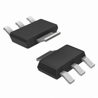
MCR08BT1 ON Semiconductor, MCR08BT1 Datasheet - Page 3

MCR08BT1
Manufacturer Part Number
MCR08BT1
Description
THYRISTOR SCR 0.8A 200V SOT223
Manufacturer
ON Semiconductor
Datasheet
1.MCR08BT1G.pdf
(6 pages)
Specifications of MCR08BT1
Scr Type
Sensitive Gate
Voltage - Off State
200V
Voltage - Gate Trigger (vgt) (max)
800mV
Voltage - On State (vtm) (max)
1.7V
Current - On State (it (rms)) (max)
800mA
Current - Gate Trigger (igt) (max)
200µA
Current - Hold (ih) (max)
5mA
Current - Off State (max)
10µA
Current - Non Rep. Surge 50, 60hz (itsm)
8A @ 60Hz
Operating Temperature
-40°C ~ 110°C
Mounting Type
Surface Mount
Package / Case
SOT-223 (3 leads + Tab), SC-73, TO-261
Current - On State (it (rms) (max)
800mA
Lead Free Status / RoHS Status
Contains lead / RoHS non-compliant
Current - On State (it (av)) (max)
-
Other names
MCR08BT1OSCT
Available stocks
Company
Part Number
Manufacturer
Quantity
Price
Company:
Part Number:
MCR08BT1
Manufacturer:
ZETEX
Quantity:
1 300
Part Number:
MCR08BT1
Manufacturer:
NXP/恩智浦
Quantity:
20 000
Company:
Part Number:
MCR08BT1G
Manufacturer:
ON
Quantity:
30 000
Part Number:
MCR08BT1G
Manufacturer:
ON/安森美
Quantity:
20 000
0.01
110
100
100
110
1.0
0.1
10
90
80
70
60
50
40
30
20
90
80
70
60
50
0
0
0
Figure 4. Current Derating, Minimum Pad Size
Figure 6. Current Derating, 2.0 cm Square Pad
CONDUCTION
ANGLE
= 30
= 30
v
T
Figure 2. On-State Characteristics
, INSTANTANEOUS ON‐STATE VOLTAGE (VOLTS)
Reference: Ambient Temperature
Reference: Ambient Temperature
I
0.1
0.1
T(AV)
I
60
T(AV)
60
90
1.0
, AVERAGE ON‐STATE CURRENT (AMPS)
, AVERAGE ON‐STATE CURRENT (AMPS)
90
50 OR 60 Hz HALFWAVE
0.2
0.2
2.0
dc
0.3
0.3
PAD AREA = 4.0 cm
OR 60 Hz HALFWAVE
TYPICAL AT T
MAX AT T
MAX AT T
180
180
dc
120
3.0
120
0.4
0.4
J
J
= 110 C
= 25 C
CONDUCTION
ANGLE
J
http://onsemi.com
= 110 C
2
, 50
4.0
0.5
0.5
3
160
150
140
130
120
110
100
110
110
100
90
80
70
60
50
40
30
85
90
80
70
60
50
40
30
20
0
0
0
Figure 5. Current Derating, 1.0 cm Square Pad
MINIMUM
FOOTPRINT = 0.076 cm
1.0
CONDUCTION
ANGLE
CONDUCTION
ANGLE
= 30
Figure 3. Junction to Ambient Thermal
Resistance versus Copper Tab Area
= 30
I
I
Reference: Ambient Temperature
T(AV)
T(AV)
2.0
0.1
0.1
60
60
DEVICE MOUNTED ON
FIGURE 1 AREA = L
PCB WITH TAB AREA
AS SHOWN
, AVERAGE ON‐STATE CURRENT (AMPS)
Figure 7. Current Derating
, AVERAGE ON‐STATE CURRENT (AMPS)
TYPICAL
MAXIMUM
90
Reference: Anode Tab
3.0
4.0
FOIL AREA (cm
0.2
0.2
2
dc
5.0
90
2
dc
0.3
6.0
0.3
2
)
50 OR 60 Hz HALFWAVE
1.0 cm
60 Hz HALFWAVE
180
7.0
180
1 2 3
2
L
4
FOIL, 50 OR
8.0
0.4
0.4
120
120
9.0
L
0.5
10
0.5


