PKM4319EPI Ericsson Power Modules, PKM4319EPI Datasheet - Page 35
PKM4319EPI
Manufacturer Part Number
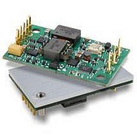
PKM4319EPI
Description
Module DC-DC 1-OUT 2.5V 15A 37.5W 8-Pin Quarter-Brick
Manufacturer
Ericsson Power Modules
Type
Step Downr
Series
PKM-Er
Datasheet
1.PKM4318HEPI.pdf
(37 pages)
Specifications of PKM4319EPI
Package
8Quarter-Brick
Output Current
15 A
Output Voltage
2.5 V
Input Voltage
36 to 75 V
Number Of Outputs
1
Output Power
37.5 W
Product
Isolated
Input Voltage Range
36 V to 75 V
Output Voltage (channel 1)
1.5 V
Output Current (channel 1)
20 A
Isolation Voltage
1.5 KV
Package / Case Size
Quarter Brick
Output Type
Isolated
Lead Free Status / Rohs Status
Lead free / RoHS Compliant
Available stocks
Company
Part Number
Manufacturer
Quantity
Price
Company:

Part Number:
PKM4319EPI
Manufacturer:
ERICSSON
Quantity:
5


General
Thermal Consideration
The PKM 4000E Series DC/DC converters are designed
to operate in a variety of thermal environments, however
sufficient cooling should be provided to help ensure reliable
operation . Heat is removed by conduction, convection and
radiation to the surrounding environment . Increased airflow
enhances the heat transfer via convection . The available load
current vs . ambient air temperature and airflow at Vin=53 V
for each model is according to the information given under
the output section . The test is done in a wind tunnel with a
cross section of 305x305mm, the DC/DC converter vertically
mounted on a 8 layer PCB with a size of 254x254mm .
Proper cooling can be verified by measuring the temperature
of selected devices . Peak temperature can occur at position
P1 and P2 . The temperature at these positions should not
exceed the recommended max values .
PKM 4000E PI Datasheet
Position
P1
P2
Transformer
Mosfet
Device
T
T
core
surface
T
critical
Max Value
110ºC
110ºC
Calculation of ambient temperature
By using the thermal resistance the maximum allowed
ambient temperature can be calculated .
1 . The powerloss is calculated by using the formula
2 . Find the value of the thermal resistance for each product in
the diagram by using the airflow speed at the output section
of the converter . Take the thermal resistance x powerloss to
get the temperature increase .
A . ((
B . 6 .1W × 5 .5°C/W = 33 .6°C
C .110°C - 33 .6°C = max ambient temperature is 76 .4°C
The real temperature will be dependent on several factors,
like PCB size and type, direction of airflow, air turbulence
etc . It is recommended to verify the temperature by testing .
3 . Max allowed calculated ambient temperature is: Max
E .g PKM 4510E PI at 1m/s:
((1/η) - 1) × output power = power losses .
η = efficiency of converter . E .g 89% = 0 .89
T
PCB
0 .89
1
of DC/DC converter – temperature increase .
) - 1) × 49 .5W = 6 .1W
EN/LZT 146 051 R7A © Ericsson Power Modules, February 2007
Related parts for PKM4319EPI
Image
Part Number
Description
Manufacturer
Datasheet
Request
R

Part Number:
Description:
37.5-150W DC/DC POWER MODULES
Manufacturer:
Ericsson Power Modules
Part Number:
Description:
DC/DC Power Supply Dual-OUT 3.3V/5V 9.6A/6.4A 40W 10-Pin
Manufacturer:
Ericsson Power Modules
Part Number:
Description:
DC/DC Power Supply Single-OUT 3.3V 20A 66W 8-Pin Quarter-Brick
Manufacturer:
Ericsson Power Modules
Datasheet:
Part Number:
Description:
DC/DC Power Supply Single-OUT 1.8V 50A 90W 11-Pin
Manufacturer:
Ericsson Power Modules
Part Number:
Description:
Module DC-DC 1-OUT 1.8V 30A 54W 9-Pin
Manufacturer:
Ericsson Power Modules

Part Number:
Description:
Module DC-DC 1-OUT 1.8V 60A 108W 11-Pin Half-Brick
Manufacturer:
Ericsson Power Modules
Datasheet:

Part Number:
Description:
Module DC-DC 1-OUT 12V 25A 300W 11-Pin Half-Brick
Manufacturer:
Ericsson Power Modules
Part Number:
Description:
Module DC-DC 1-OUT 5V 20A 100W Quarter-Brick
Manufacturer:
Ericsson Power Modules

Part Number:
Description:
Module DC-DC 1-OUT 12V 6A 72W 8-Pin 1/8-Brick
Manufacturer:
Ericsson Power Modules
Datasheet:
Part Number:
Description:
Module DC-DC 1-OUT 5.05V 2A 10W 18-Pin SMD
Manufacturer:
Ericsson Power Modules
Part Number:
Description:
Manufacturer:
Ericsson Power Modules
Datasheet:

Part Number:
Description:
Module DC-DC 1-OUT 5V 60A 300W 11-Pin Half-Brick Tray
Manufacturer:
Ericsson Power Modules
Part Number:
Description:
Module DC-DC 1-OUT 12V 1A 12W 18-Pin
Manufacturer:
Ericsson Power Modules
Datasheet:
Part Number:
Description:
Module DC-DC 2-OUT 12V/-12V 0.25A 6W 18-Pin SMD
Manufacturer:
Ericsson Power Modules
Part Number:
Description:
Module DC-DC 1-OUT 28V 11A 310W 11-Pin Half-Brick Tray
Manufacturer:
Ericsson Power Modules
Datasheet: