ZY7115HG-T2 POWER ONE, ZY7115HG-T2 Datasheet - Page 29
ZY7115HG-T2
Manufacturer Part Number
ZY7115HG-T2
Description
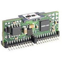
Module DC-DC 1-OUT 0.5V to 5.5V 15A 25-Pin SMT T/R
Manufacturer
POWER ONE
Datasheet
1.ZY7115HG-T2.pdf
(34 pages)
Specifications of ZY7115HG-T2
Product
Non-Isolated / POL
Input Voltage Range
3 V to 13.2 V
Number Of Outputs
1
Output Voltage (channel 1)
0.5 V to 5.5 V
Output Current (channel 1)
15 A
Package / Case Size
8 mm x 32 mm x 14 mm
Output Voltage
0.5 V to 5.5 V
Lead Free Status / Rohs Status
Lead free / RoHS Compliant


8.5
The POL converters are equipped with the digital
current share function. To activate the current share,
interconnect the CS pins of the POLs connected in
parallel. The digital signal transmitted over the CS
line sets output currents of all POLs to the same
level.
When POLs are connected in parallel, they must be
included in the same parallel bus in the GUI System
Configuration window shown in Figure 56. In this
case, the GUI automatically copies parameters of
one POL onto all POLs connected to the parallel
bus.
performance parameters for POLs connected in
parallel except for interleave and load regulation
settings that are independent. The interleave allows
to reduce and move the output noise of the
converters
frequencies as shown in Figure 52 and Figure 53.
The load regulation allows controlling the current
share loop gain in case of small signal oscillations. It
is recommended to always add a small amount of
load regulation to one of the converters connected in
parallel to reduce loop gain and therefore improve
stability.
MDS-0006 Rev. 3.6, 02-Jul-10
Current Share
It makes it impossible to configure different
connected
in
parallel
www.power-one.com
to
ZY7115 15A DC-DC Intelligent POL Data Sheet
higher
3V to 13.2V Input
8.6
The
performance parameters such as output voltage,
output current, and temperature.
The output voltage is measured at the output sense
pins, output current is measured using the ESR of
the output inductor and temperature is measured by
the thermal sensor built into the controller IC. Output
current readings are adjusted based on temperature
readings to compensate for the change of ESR of
the inductor with temperature.
An 8-Bit Analog to Digital Converter (ADC) converts
the output voltage, output current, and temperature
into a digital signal to be transmitted via the serial
interface.
frequency of 1 kHz for all three values.
Monitored parameters are stored in registers (VOM,
IOM, and TMON) that are continuously updated. If
the Retrieve Monitoring bits in the GUI Group
Configuration window shown in Figure 57 are
checked, those registers are being copied into the
ring buffer located in the DPM. Contents of the ring
buffer can be displayed in the GUI IBS Monitoring
Window shown in Figure 58 or it can be read directly
via the I
as described in the ‘”DPM Programming Manual”.
POL
Performance Parameters Monitoring
2
C bus using high and low level commands
The ADC allows a minimum sampling
converters
0.5V to 5.5V Output
can
monitor
Page 29 of 34
their
own
Related parts for ZY7115HG-T2
Image
Part Number
Description
Manufacturer
Datasheet
Request
R

Part Number:
Description:
SWITCHING POWER SUPPLIES, SINGLE OUTPUT, 80 WATTS
Manufacturer:
POWER ONE
Datasheet:
Part Number:
Description:
HAS SERIES - 30 WATT
Manufacturer:
POWER ONE
Datasheet:
Part Number:
Description:
SINGLE OUTPUT
Manufacturer:
POWER ONE
Datasheet:

Part Number:
Description:
BRS DC/DC converters(1.5 WATT)
Manufacturer:
Power-One
Datasheet:
Part Number:
Description:
3...15 Watt DC-DC Converter
Manufacturer:
Power-One
Datasheet:
Part Number:
Description:
HBS SERIES - 100 WATT
Manufacturer:
Power-One
Datasheet:
Part Number:
Description:
3...15 Watt DC-DC Converter
Manufacturer:
Power-One
Datasheet:
Part Number:
Description:
BUS DC/DC converters(3 WATT)
Manufacturer:
Power-One
Datasheet:
Part Number:
Description:
HES SERIES 150 WATT
Manufacturer:
Power-One
Datasheet:
Part Number:
Description:
1.25 WATT
Manufacturer:
Power-One
Datasheet: