24140 Cinch Connectors, 24140 Datasheet - Page 119
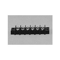
24140
Manufacturer Part Number
24140
Description
Manufacturer
Cinch Connectors
Type
Barrier Stripr
Datasheet
1.24140.pdf
(282 pages)
Specifications of 24140
Number Of Contacts
24POS
Number Of Contact Rows
2
Termination Method
Screw
Mounting Style
Panel
Contact Pitch (mm)
9.53mm
Current Rating (max)
15A
Operating Temp Range
-48C to 148C
Housing Material
Phenolic
Body Orientation
Straight
Operating Voltage (max)
250VAC
Product Height (mm)
28.58mm
Product Length (mm)
245.28mm
Wire Gauge
16
Lead Free Status / RoHS Status
Compliant
Available stocks
Company
Part Number
Manufacturer
Quantity
Price
Company:

Part Number:
241402B91200G
Manufacturer:
ATH
Quantity:
1 020
Company:
Part Number:
241402B92200G
Manufacturer:
ATH
Quantity:
414
Company:
Part Number:
241404B91200G
Manufacturer:
ATH
Quantity:
300
Company:
Part Number:
241404B92200G
Manufacturer:
ATH
Quantity:
262
Company:
Part Number:
241409B91200G
Manufacturer:
ATH
Quantity:
100


D-subminiature Metal Shell
Overmold Kits
D*A and HTD Series
Shield Covers: Steel (stamped) with tin/lead finish
Ferrule: Brass
Call Toll Free: 1 (800) 323-9612
Dimensions
Overmold Shielding Kits
Positions
15 Plug
15 Socket
25 Plug
25 Socket
37 Plug
37 Socket
9 Plug
9 Socket
Cinch overmold kits enable you to overmold the connector of the cable assembly for less
material and process cost (versus a metal backshell), improved appearance, and improved
shielding of the connector to help meet RFI/EMI requirements.
An Overmold Kit catalog number consists of:
-
-
-
You will also need to order the following:
-
-
-
-
All specifications on the connector portion of the overmold kit can be found on pages 4-16 thru
4-17 for HPD 1.5 density and pages 4-20 thru 4-21 for D*A series.
D*A or HTD Crimp and Poke connector.
Inside shielding cover.
Outside shielding cover.
Crimp and Poke stamped contacts must be ordered separately on page 4-22 for D*A
and page 4-18 for HTD connectors.
Ferrules are required, but must be ordered separately according to the size necessary to
accommodate the wire. See page 4-25.
Termination tooling is required to crimp the wires on the connector.
A hand tool and appropriate crimping die are required for crimping the ferrule.
0.270
0.285
0.270
0.285
0.275
0.285
0.275
0.285
in
C
6.86
7.24
6.86
7.24
6.99
7.24
6.99
7.24
mm
0.705 17.91
0.705 17.91
1.050 26.67
1.050 26.67
1.590 40.39
1.590 40.39
2.240 56.90
2.240 56.90
in
D
mm
4-24
1.320 33.53
1.320 33.53
1.320 33.53
1.320 33.53
1.320 33.53
1.320 33.53
1.620 41.15
1.620 41.15
in
E
mm
0.520 13.21
0.520 13.21
0.520 13.21
0.520 13.21
0.520 13.21
0.520 13.21
0.750 19.05
0.750 19.05
in
F
mm
Deg.
75°
75°
58°
58°
40°
40°
32°
32°
G
0.440
0.440
0.440
0.440
0.440
0.440
0.520
0.520
in
H
11.18
11.18
11.18
11.18
11.18
11.18
13.21
13.21
mm
Related parts for 24140
Image
Part Number
Description
Manufacturer
Datasheet
Request
R

Part Number:
Description:
Standard Card Edge Connectors CINCH BLK CARD GUIDE
Manufacturer:
Cinch Connectors

Part Number:
Description:
TERMINAL BLOCK JUMPER TYPE F
Manufacturer:
Cinch Connectors
Datasheet:
Part Number:
Description:
D-Subminiature Connectors MCHNED PIN 20-24AWG
Manufacturer:
Cinch Connectors
Datasheet:
Part Number:
Description:
Terminal Block,4 Contacts,0.44 Pitch
Manufacturer:
Cinch Connectors
Datasheet:

Part Number:
Description:
Terminal Block,8 Contacts,0.375 Pitch
Manufacturer:
Cinch Connectors
Datasheet: