24140 Cinch Connectors, 24140 Datasheet - Page 198
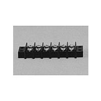
24140
Manufacturer Part Number
24140
Description
Manufacturer
Cinch Connectors
Type
Barrier Stripr
Datasheet
1.24140.pdf
(282 pages)
Specifications of 24140
Number Of Contacts
24POS
Number Of Contact Rows
2
Termination Method
Screw
Mounting Style
Panel
Contact Pitch (mm)
9.53mm
Current Rating (max)
15A
Operating Temp Range
-48C to 148C
Housing Material
Phenolic
Body Orientation
Straight
Operating Voltage (max)
250VAC
Product Height (mm)
28.58mm
Product Length (mm)
245.28mm
Wire Gauge
16
Lead Free Status / RoHS Status
Compliant
Available stocks
Company
Part Number
Manufacturer
Quantity
Price
Company:

Part Number:
241402B91200G
Manufacturer:
ATH
Quantity:
1 020
Company:
Part Number:
241402B92200G
Manufacturer:
ATH
Quantity:
414
Company:
Part Number:
241404B91200G
Manufacturer:
ATH
Quantity:
300
Company:
Part Number:
241404B92200G
Manufacturer:
ATH
Quantity:
262
Company:
Part Number:
241409B91200G
Manufacturer:
ATH
Quantity:
100


Ordering Information
Dura-Con
High Reliability
All-Plastic
Contact Arrangements
(Face view of pin insulator)
(Use reverse order for socket)
** - See p. 5-12 for std. hardware dims. See p. 5-13 for non-std. hardware & p. 5-31 for Mil spec. hardware both sold separately.
***- Length Tolerance: solid wire = ± 3/32”, standard wire = ± 1/4”.
* - Indicates Cinch std. option.
Cinch Dura-Con D Connector
Insulator Type
*D = Thermoplastic
Glass Reinforced
Mounting Type
*A = Screw Mount Flange
No. of Contacts
9, 15, 21, 25, 31, 37, 51
Contact Type
P – Pin (Plug)
S – Socket (Receptacle)
Wire Size in AWG
5 = 25 AWG Solid Copper
6 = 26 AWG Stranded
S = Solder Cup (Skip to Mounting Hardware)
Wire Type
E = MIL-W-16878/4, 7 Strand
C = Solid Copper - Uninsulated
(
Consult factory for non-standard wire types)
DC D A 37 P 6 E 2 -18.0 K
.050" (1.27mm) Density
Solder Cup/Wire
D-Microminiature
5-5
Call Toll Free: 1 (800) 323-9612
Mounting Hardware**
B = No Hardware
F = Float Mount
R = Reverse Float Mount
K = Jackscrew (Standard)
L = Jackscrew (Low Profile)
P = Jackpost, MIL-C-83513/5-07
Lead Length in inches***
00.5 Solid copper wire only
01.0 Solid copper wire only
02.0 Solid copper wire only
18.0 Stranded wire only
24.0 Stranded wire only
36.0 Stranded wire only
48.0 Stranded wire only
Insulation
Color or Wire Finish
*2 = Yellow (Stranded Wire)
*4 = Gold-Plated (Solid Wire Only)
*5 = Color Coded Per MIL-Std. (681)
System 1. (Stranded Wire Only)
1 = White
3 = Tin-Plated
Related parts for 24140
Image
Part Number
Description
Manufacturer
Datasheet
Request
R

Part Number:
Description:
Standard Card Edge Connectors CINCH BLK CARD GUIDE
Manufacturer:
Cinch Connectors

Part Number:
Description:
TERMINAL BLOCK JUMPER TYPE F
Manufacturer:
Cinch Connectors
Datasheet:
Part Number:
Description:
D-Subminiature Connectors MCHNED PIN 20-24AWG
Manufacturer:
Cinch Connectors
Datasheet:
Part Number:
Description:
Terminal Block,4 Contacts,0.44 Pitch
Manufacturer:
Cinch Connectors
Datasheet:

Part Number:
Description:
Terminal Block,8 Contacts,0.375 Pitch
Manufacturer:
Cinch Connectors
Datasheet: