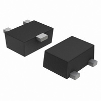
DTC114EM3T5G ON Semiconductor, DTC114EM3T5G Datasheet

DTC114EM3T5G
Specifications of DTC114EM3T5G
DTC114EM3T5GOSTR
Available stocks
Related parts for DTC114EM3T5G
DTC114EM3T5G Summary of contents
Page 1
DTA114EM3T5G Series Preferred Devices Digital Transistors (BRT) PNP Silicon Surface Mount Transistors with Monolithic Bias Resistor Network This new series of digital transistors is designed to replace a single device and its external resistor bias network. The digital transistor contains ...
Page 2
ORDERING INFORMATION, DEVICE MARKING AND RESISTOR VALUES Device Marking DTA114EM3T5G 6A DTA124EM3T5G* 6B DTA144EM3T5G 6C DTA114YM3T5G 6D DTA114TM3T5G 6E DTA143TM3T5G* 6F DTA123EM3T5G* 6H DTA143EM3T5G* 6J DTA143ZM3T5G* 6K DTA124XM3T5G 6L DTA123JM3T5G* 6M DTA115EM3T5G 6N DTA144WM3T5G* 6P *Available upon request †For information ...
Page 3
ELECTRICAL CHARACTERISTICS Characteristic OFF CHARACTERISTICS Collector−Base Cutoff Current ( Collector−Emitter Cutoff Current ( Emitter−Base Cutoff Current ( mA, I Collector−Base ...
Page 4
ELECTRICAL CHARACTERISTICS Characteristic Input Resistor Resistor Ratio DTA114EM3T5G/DTA124EM3T5G/DTA144EM3T5G / DTA115EM3T5G DTA114YM3T5G DTA114TM3T5G/DTA143TM3T5G DTA123EM3T5G/DTA143EM3T5G DTA143ZM3T5G DTA124XM3T5G DTA123JM3T5G DTA144WM3T5G 300 250 200 150 100 50 0 −50 DTA114EM3T5G Series ( unless otherwise noted) (Continued) A Symbol DTA114EM3T5G R1 DTA124EM3T5G ...
Page 5
TYPICAL ELECTRICAL CHARACTERISTICS − DTA114EM3T5G − COLLECTOR CURRENT (mA) C Figure 2. V versus I CE(sat ...
Page 6
TYPICAL ELECTRICAL CHARACTERISTICS − DTA124EM3T5G − 0.1 0. COLLECTOR CURRENT (mA) C Figure 7. V versus I CE(sat ...
Page 7
TYPICAL ELECTRICAL CHARACTERISTICS − DTA144EM3T5G − 0.1 0. COLLECTOR CURRENT (mA) C Figure 12. V versus I CE(sat) 1 0.8 0.6 0.4 0.2 0 ...
Page 8
TYPICAL ELECTRICAL CHARACTERISTICS − DTA114YM3T5G 0 0.01 0.001 COLLECTOR CURRENT (mA) C Figure 17. V versus I CE(sat) 4.5 4 3.5 3 2.5 2 1.5 ...
Page 9
TYPICAL ELECTRICAL CHARACTERISTICS — DTA115EM3T5G 1 0.1 − COLLECTOR CURRENT (mA) C Figure 23. Maximum Collector Voltage versus Collector Current 1.2 1.0 0.8 0.6 0.4 0 ...
Page 10
TYPICAL ELECTRICAL CHARACTERISTICS — DTA144WM3T5G − COLLECTOR CURRENT (mA) C Figure 28. Maximum Collector Voltage versus Collector Current 1.4 1.2 1.0 0.8 ...
Page 11
... SOLDERING FOOTPRINT* 0.40 0.0157 0.40 0.0157 0.40 0.0157 *For additional information on our Pb−Free strategy and soldering details, please download the ON Semiconductor Soldering and Mounting Techniques Reference Manual, SOLDERRM/D. SOT−723 CASE 631AA−01 ISSUE A NOTES: 1. DIMENSIONING AND TOLERANCING PER ANSI Y14.5M, 1982. ...
Page 12
... Fax: 303−675−2176 or 800−344−3867 Toll Free USA/Canada Email: orderlit@onsemi.com DTA114EM3T5G Series N. American Technical Support: 800−282−9855 Toll Free USA/Canada Japan: ON Semiconductor, Japan Customer Focus Center 2−9−1 Kamimeguro, Meguro−ku, Tokyo, Japan 153−0051 Phone: 81−3−5773−3850 http://onsemi.com 12 ON Semiconductor Website: http://onsemi ...


