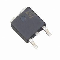
T405-600B-TR STMicroelectronics, T405-600B-TR Datasheet - Page 4

T405-600B-TR
Manufacturer Part Number
T405-600B-TR
Description
TRIAC 600V 4A 5MA D-PAK
Manufacturer
STMicroelectronics
Type
TRIACr
Datasheet
1.T410-600B-TR.pdf
(10 pages)
Specifications of T405-600B-TR
Triac Type
Logic - Sensitive Gate
Mounting Type
Surface Mount
Configuration
Single
Current - Hold (ih) (max)
10mA
Voltage - Off State
600V
Current - Gate Trigger (igt) (max)
5mA
Current - Non Rep. Surge 50, 60hz (itsm)
30A, 31A
Current - On State (it (rms)) (max)
4A
Voltage - Gate Trigger (vgt) (max)
1.3V
Package / Case
TO-252-3, DPak (2 Leads + Tab), SC-63
Current - On State (it (rms) (max)
4A
Repetitive Peak Off-state Volt
600V
Off-state Voltage
600V
Hold Current
10mA
Gate Trigger Current (max)
5mA
Gate Trigger Voltage (max)
1.3V
Package Type
DPAK
Peak Repeat Off Current
5uA
Peak Surge On-state Current (max)
31A
On State Voltage(max)
1.56@5.5AV
Mounting
Surface Mount
Pin Count
2 +Tab
Operating Temp Range
-40C to 125C
Operating Temperature Classification
Automotive
Lead Free Status / RoHS Status
Lead free / RoHS Compliant
Other names
497-2505-2
Available stocks
Company
Part Number
Manufacturer
Quantity
Price
Part Number:
T405-600B-TR
Manufacturer:
ST
Quantity:
20 000
T4 Series
Figure 1: Maximum power dissipation versus
RMS on-state current (full cycle)
Figure 3: RMS on-state current versus ambient
temperature (printed circuit board FR4, copper
thickness: 35µm) (full cycle)
Figure 5: On-state characteristics (maximum
values)
4/10
30.0
10.0
6
5
4
3
2
1
0
2.0
1.8
1.6
1.4
1.2
1.0
0.8
0.6
0.4
0.2
0.0
1.0
0.0
0.1
P(W)
I
0
0.0
T(RMS)
I
TM
R = 120 m
V = 0.90V
d
to
0.5
(A)
T max.
T =
j
j
0.5
(A)
T max.
j
Ω
25
1.0
1.0
1.5
T = 25°C
1.5
j
50
2.0
I
.
T(RMS)
T (°C)
C
V
2.0
TM
2.5
(A)
(V)
75
3.0
2.5
3.5
3.0
100
4.0
(S=0.5CM )
3.5
DPAK
4.5
2
125
4.0
5.0
Figure 2: RMS on-state current versus case
temperature (full cycle)
Figure 4: Relative variation of thermal
impedance versus pulse duration
Figure 6: Surge peak on-state current versus
number of cycles
1E+0
4.5
4.0
3.5
3.0
2.5
2.0
1.5
1.0
0.5
0.0
35
30
25
20
15
10
1E-2
1E-1
0
5
1
I
0
I
TSM
T(RMS)
1E-2
K=[Z /R
TO-220AB / DPAK / IPAK
(A)
th
(A)
Repetitive
T =110°C
C
25
th
1E-1
R
]
th(j-c)
10
ISOWATT220AB
Number of cycles
Non repetitive
T initial=25°C
50
j
1E+0
T (°C)
C
DPAK / IPAK
t (s)
p
TO-220AB / DPAK / IPAK
75
1E+1
100
ISOWATT220AB
TO-220AB / ISOWATT220AB
R
th(j-a)
100
t=20ms
1E+2
One cycle
5E+2
1000
125


