103308-6 TE Connectivity, 103308-6 Datasheet - Page 117
103308-6
Manufacturer Part Number
103308-6
Description
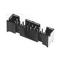
Conn Shrouded Header HDR 26 POS 2.54mm Solder ST Thru-Hole
Manufacturer
TE Connectivity
Type
Shrouded Headerr
Series
AMP-LATCHr
Specifications of 103308-6
Pitch
2.54 mm
Number Of Rows
2
Number Of Contacts
26
Gender
HDR
Contact Plating
Gold Over Nickel/Gold Over Palladium Nickel
Termination Method
Solder
Pitch (mm)
2.54mm
Number Of Contact Rows
2
Mounting Style
Through Hole
Body Orientation
Straight
Operating Temp Range
-65C to 105C
Current Rating (max)
1/ContactA
Contact Material
Copper Alloy
Housing Material
Thermoplastic
Housing Color
Black
Product Height (mm)
9.77mm
Product Length (mm)
40.64mm
Product Depth (mm)
9.14mm
Connector Type
Wire To Board
Contact Termination
Through Hole
No. Of Contacts
26
No. Of Rows
2
Pitch Spacing
2.54mm
Rohs Compliant
No
Product Line
AMP-LATCH
Profile
Low
Pcb Mounting Orientation
Vertical
Pcb Mount Retention
Without
Mating Connector Lock
Without
Housing Style
4-Sided
Ejection Latches
Without
Post Size (mm [in])
0.64 [.025]
Shrouded
Yes
[shrouded] End Dimension (mm [in])
3.81 [0.150]
Current Rating (a)
1
Insulation Resistance (m?)
5,000
Termination Post Length (mm [in])
3.05 [0.120]
Solder Tail Contact Plating
Tin-Lead over Nickel
Header Type
Pin Header
Number Of Positions
26
Centerline, Matrix (mm [in])
2.54 x 2.54 [.100 x .100]
Daisy Chain
With
Preloaded
Yes
Contact Plating, Mating Area, Material
Gold (15), Gold Flash over Palladium Nickel
Contact Shape
Square
Contact Base Material
Copper Alloy
Connector Style
Header - Pin
Mating Alignment Type
Center, Dual Polarizing Bar
Mating Alignment
With
Ul Flammability Rating
UL 94V-0
Rohs/elv Compliance
ELV compliant, 5 of 6 Compliant
Lead Free Solder Processes
Not suitable for lead free processing
Approved Standards
UL E28476, CSA LR7189
Operating Temperature (°c)
-65 – +105
Temperature Rating
Standard
Lead Free Status / RoHS Status
Not Compliant
Available stocks
Company
Part Number
Manufacturer
Quantity
Price


5
200
Catalog 1307819
Revised 6-04
www.tycoelectronics.com
Closed Dual Entry, Side and
End Stackable Low Profile,
.100 x .100 [2.54 x 2.54]
Centerline, .150 [3.81] Tine
S p a c i n g
Photo 110925
Material and Finish:
Housing—Black thermoplastic,
94V-0 rated
Contacts—Phosphor bronze,
plated as follows:
Plating A—Duplex .000030 [0.00076]
gold on contact area, .000150-.000300
[0.00381-0.00762] tin-lead on solder
area all over .000050 [0.00127] nickel
Plating B—Duplex .000010
[0.000254] gold on contact area,
.000150-.000300 [0.00381-0.00762]
tin-lead on solder area all over .000050
[0.00127] nickel
Plating C—.000100-.000200
[0.00254-0.00508] tin-lead over
.000050 [0.00127] nickel
Related Product Data:
Mateable Headers—Refer
to the Mating Post Selection Guide
(page 89)
Performance Characteristics—page
191
Technical Documents
Product Specification 108-25022
Application Specification
114-25018
(page 294):
Dimensions are in inches and
millimeters unless otherwise
specified. Values in brackets
are metric equivalents.
[
.075
.060
1.90
AMPMODU Interconnection System
[5.03]
Notes: 1. Tyco Electronics recommends mating gold or duplex plated headers with duplex plated receptacle
Mod. IV Receptacle Assemblies, Double-Row,
.100 x .100 [2.54 x 2.54] Centerline
.198
No. of
P o s .
+.005
+0.13
-.000
- 0.00
[2.54]
1 0
1 2
1 4
1 6
1 8
2 0
2 2
2 4
2 6
2 8
3 0
3 2
3 4
3 6
3 8
4 0
.100
2
4
6
8
]
2. To obtain the minimum mating post length, add .020 [0.51] (not including the post lead in chamfer) to
for Bottom Entry or Pass Through Applications
Typ.
Dia.
assemblies.
the maximum point-of-contact dimension, and .062 [1.57] for recommended board thickness if used in
bottom entry application.
*±.003 [±0.08] tolerances not to accumulate
Recommended PC Board Hole Layout
1 . 0 0 0 [ 2 5 . 4 0 ]
1 . 1 0 0 [ 2 7 . 9 4 ]
1 . 2 0 0 [ 3 0 . 4 8 ]
1 . 3 0 0 [ 3 3 . 0 2 ]
1 . 4 0 0 [ 3 5 . 5 6 ]
1 . 5 0 0 [ 3 8 . 1 0 ]
1 . 6 0 0 [ 4 0 . 6 4 ]
1 . 7 0 0 [ 4 3 . 1 8 ]
1 . 8 0 0 [ 4 5 . 7 2 ]
1 . 9 0 0 [ 4 8 . 2 6 ]
2 . 0 0 0 [ 5 0 . 8 0 ]
.100 [ 2 . 5 4 ]
. 2 0 0 [ 5 . 0 8 ]
. 3 0 0 [ 7 . 6 2 ]
. 4 0 0 [ 1 0 . 1 6 ]
. 5 0 0 [ 1 2 . 7 0 ]
. 6 0 0 [ 1 5 . 2 4 ]
. 7 0 0 [ 1 7 . 7 8 ]
. 8 0 0 [ 2 0 . 3 2 ]
. 9 0 0 [ 2 2 . 8 6 ]
[1.27]
Max.
.050
Typ.
within one connector pattern.
A
Dimensions are shown for
reference purposes only.
Specifications subject
to change.
D i m e n s i o n s
[2.54]
B
A
.100
Typ.
1 . 0 0 0 [ 2 5 . 4 0 ]
1 . 1 0 0 [ 2 7 . 9 4 ]
1 . 2 0 0 [ 3 0 . 4 8 ]
1 . 3 0 0 [ 3 3 . 0 2 ]
1 . 4 0 0 [ 3 5 . 5 6 ]
1 . 5 0 0 [ 3 8 . 1 0 ]
1 . 6 0 0 [ 4 0 . 6 4 ]
1 . 7 0 0 [ 4 3 . 1 8 ]
1 . 8 0 0 [ 4 5 . 7 2 ]
1 . 9 0 0 [ 4 8 . 2 6 ]
. 1 0 0 [ 2 . 5 4 ]
.200 [ 5 . 0 8 ]
. 3 0 0 [ 7 . 6 2 ]
. 4 0 0 [ 1 0 . 1 6 ]
. 5 0 0 [ 1 2 . 7 0 ]
. 6 0 0 [ 1 5 . 2 4 ]
. 7 0 0 [ 1 7 . 7 8 ]
. 8 0 0 [ 2 0 . 3 2 ]
. 9 0 0 [ 2 2 . 8 6 ]
B
—
USA: 1-800-522-6752
Canada: 1-905-470-4425
Mexico: 01-800-733-8926
C. America: 52-55-5-729-0425
[6.22]
.245
Typ.
(Standoffs)
[2.54±0.08]
.100±.003
[0.51]
.020
Typ.
[2.54]
.100
Typ.
1 - 5 3 5 5 4 2 - 0
1 - 5 3 5 5 4 2 - 1
1 - 5 3 5 5 4 2 - 2
1 - 5 3 5 5 4 2 - 3
1 - 5 3 5 5 4 2 - 4
1 - 5 3 5 5 4 2 - 5
1 - 5 3 5 5 4 2 - 6
1 - 5 3 5 5 4 2 - 7
1 - 5 3 5 5 4 2 - 8
1 - 5 3 5 5 4 2 - 9
2 - 5 3 5 5 4 2 - 0
[0.89±0.08]
Plating A
.035±.003
5 3 5 5 4 2 - 1
5 3 5 5 4 2 - 2
5 3 5 5 4 2 - 3
5 3 5 5 4 2 - 4
5 3 5 5 4 2 - 5
5 3 5 5 4 2 - 6
5 3 5 5 4 2 - 7
5 3 5 5 4 2 - 8
5 3 5 5 4 2 - 9
(Localized Gold
Plate Area)
Recommended PC Board Hole Layout
[3.77]
[2.72]
.107
Typ.
.148
Typ.
Dia. Typ.
Contact Plating/Part Nos.
[2.54]
.100
Typ.
South America: 55-11-3611-1514
Hong Kong: 852-2735-1628
Japan: 81-44-844-8013
UK: 44-141-810-8967
1 - 1 4 7 0 9 5 - 0
1 - 1 4 7 0 9 5 - 1
1 - 1 4 7 0 9 5 - 2
1 - 1 4 7 0 9 5 - 3
1 - 1 4 7 0 9 5 - 4
1 - 1 4 7 0 9 5 - 5
1 - 1 4 7 0 9 5 - 6
1 - 1 4 7 0 9 5 - 7
1 - 1 4 7 0 9 5 - 8
1 - 1 4 7 0 9 5 - 9
2 - 1 4 7 0 9 5 - 0
for Top Entry
Plating B
1 4 7 0 9 5 - 1
1 4 7 0 9 5 - 2
1 4 7 0 9 5 - 3
1 4 7 0 9 5 - 4
1 4 7 0 9 5 - 5
1 4 7 0 9 5 - 6
1 4 7 0 9 5 - 7
1 4 7 0 9 5 - 8
1 4 7 0 9 5 - 9
Point of
Contact
B
[3.30±0.25]
1 - 1 4 7 0 9 6 - 0
1 - 1 4 7 0 9 6 - 1
1 - 1 4 7 0 9 6 - 2
1 - 1 4 7 0 9 6 - 3
1 - 1 4 7 0 9 6 - 4
1 - 1 4 7 0 9 6 - 5
1 - 1 4 7 0 9 6 - 6
1 - 1 4 7 0 9 6 - 7
1 - 1 4 7 0 9 6 - 8
1 - 1 4 7 0 9 6 - 9
2 - 1 4 7 0 9 6 - 0
.130±.010
Plating C
1 4 7 0 9 6 - 1
1 4 7 0 9 6 - 2
1 4 7 0 9 6 - 3
1 4 7 0 9 6 - 4
1 4 7 0 9 6 - 5
1 4 7 0 9 6 - 6
1 4 7 0 9 6 - 7
1 4 7 0 9 6 - 8
1 4 7 0 9 6 - 9
[3.81]
.150
Typ.
Typ.
[3.81]
.150
Typ.
Related parts for 103308-6
Image
Part Number
Description
Manufacturer
Datasheet
Request
R

Part Number:
Description:
Conn Shrouded Header HDR 10 POS 2.54mm Solder ST Thru-Hole
Manufacturer:
TE Connectivity
Datasheet:

Part Number:
Description:
Conn Shrouded Header HDR 14 POS 2.54mm Solder ST Thru-Hole
Manufacturer:
TE Connectivity
Datasheet:
Part Number:
Description:
Conn Shrouded Header HDR 16 POS 2.54mm Solder ST Thru-Hole
Manufacturer:
TE Connectivity
Datasheet:
Part Number:
Description:
Conn Shrouded Header HDR 40 POS 2.54mm Solder ST Thru-Hole
Manufacturer:
TE Connectivity
Datasheet:
Part Number:
Description:
Conn Shrouded Header HDR 20 POS 2.54mm Solder ST Thru-Hole
Manufacturer:
TE Connectivity
Datasheet:

Part Number:
Description:
High Speed / Modular Connectors 30P HEADER ASSY
Manufacturer:
TE Connectivity
Datasheet:

Part Number:
Description:
High Speed / Modular Connectors REC 6X005P R/A LT B-PLANE HS3
Manufacturer:
TE Connectivity
Datasheet:

Part Number:
Description:
High Speed / Modular Connectors 2MM HM RCPT 50P R/A AU
Manufacturer:
TE Connectivity
Datasheet:

Part Number:
Description:
High Speed / Modular Connectors 2MM HM RCPT 50P R/A AU
Manufacturer:
TE Connectivity
Datasheet:


Part Number:
Description:
Manufacturer:
TE Connectivity
Datasheet:


Part Number:
Description:
Manufacturer:
TE Connectivity
Datasheet:

Part Number:
Description:
Manufacturer:
TE Connectivity
Datasheet:

Part Number:
Description:
Manufacturer:
TE Connectivity
Datasheet: