5-534998-7 TE Connectivity, 5-534998-7 Datasheet - Page 56
5-534998-7
Manufacturer Part Number
5-534998-7
Description
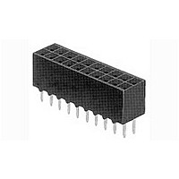
Conn Socket Strip RCP 14 POS 2.54mm Solder ST Thru-Hole Gang of Tubes
Manufacturer
TE Connectivity
Type
Socket Stripr
Series
AMPMODU Mod IVr
Datasheet
1.5-87589-1.pdf
(96 pages)
Specifications of 5-534998-7
Pitch
2.54 mm
Number Of Rows
2
Number Of Contacts
14
Gender
RCP
Contact Plating
Gold Over Nickel
Termination Method
Solder
Pitch Spacing
2.54mm
No. Of Rows
2
No. Of Contacts
14
Contact Termination
Through Hole
Contact Material
Phosphor Bronze
Rohs Compliant
Yes
Product Type
Receptacles / Sockets - PCB
Number Of Positions / Contacts
14
Mounting Style
Through Hole - Solder
Mounting Angle
Vertical
Termination Style
Solder Pin
Housing Material
Polyester Polycyclohexylenedimethylene Terephthalate (PCT)
Current Rating
2 A
Operating Temperature Range
- 65 C to + 105 C
Connector Series
Mod IV
Profile
Low
Mounting Pattern (mm [in])
2.54 x 2.54 [.100 x .100]
Sealed
No
Holddown Feature
Without
Pcb Mounting Orientation
Vertical
Pcb Mount Retention
With
Termination Method To Pc Board
Through Hole - Solder
Closed Entry
With
Board Standoff
With
Stackable
Yes
Contact - Rated Current (a)
2
Contact Resistance (m?)
12
Insulation Resistance (m?)
5,000
Dielectric Withstanding Voltage (v)
750
Termination Post Length (mm [in])
3.18 [0.125]
Solder Tail Contact Plating
Tin over Nickel
Connector Height (mm [in])
6.22 [0.245]
Number Of Positions
14
Centerline, Matrix (mm [in])
2.54 x 2.54 [.100 x .100]
Pcb Mount Retention Type
Retention Solder Tails
Contact Plating, Mating Area, Material
Gold (30)
Contact Base Material
Phosphor Bronze
Housing Entry Style
Top
Ul Flammability Rating
UL 94V-0
Housing Color
Black
Government/industry Qualification
No
Rohs/elv Compliance
RoHS compliant, ELV compliant
Lead Free Solder Processes
Wave solder capable to 240°C, Wave solder capable to 260°C, Wave solder capable to 265°C
Rohs/elv Compliance History
Always was RoHS compliant
Approved Standards
UL E28476, CSA LE7189
Operating Temperature (°c)
-65 – +105
Pcb Thickness, Recommended (mm [in])
1.57 [0.062]
High Temperature Compatible
No
Packaging Method
Gang of Tubes
Lead Free Status / Rohs Status
Details
Available stocks
Company
Part Number
Manufacturer
Quantity
Price
Company:

Part Number:
5-534998-7
Manufacturer:
TE Connectivity AMP Connectors
Quantity:
543


5
140
Right-Angle, 4-Sided
.025 [0.64] Sq. Posts
Material and Finish
Housing & Latches — Black
thermoplastic, 94V-0 rated
Contacts — Brass or phosphor bronze
(at Tyco Electronics’ option); Duplex
.000030 [0.00076] gold on mating end,
.000100 [0.00254] min. tin on
termination end, with entire contact
underplated .000050 [0.00127] nickel
Related Product Data
Electrical Characteristics —
page 134
Mateable Connectors —
AMPMODU Wire-Applied
Receptacles — page 220
Mounting Information
4-24 self-tapping screws
and 2-56 bolts and nuts are
available for mounting
straight-thru pin headers of
pc boards. Typical applica-
tions and part nos. for
ordering this hardware are
presented below.
Note: 2-56 bolts and nuts may be
used to mount pin headers with and
without latches. If latches are to be
used, the bolts must be positioned in
the pin header before the latches are
installed.
Note: All part numbers are RoHS
Catalog 1307819
Revised 8-08
www.tycoelectronics.com
compliant.
without Latches
with Latches
Pin Header
Pin Header
are metric equivalents.
Dimensions are in inches and
millimeters unless otherwise
specified. Values in brackets
[8.53]
.336
AMPMODU Interconnection System
Universal Ejection Style Pin Headers, Military, Center and Dual Polarized,
.100 x .100 [2.54 x 2.54] Centers
Notes: 1. Pin headers in 10- and 14-position sizes have only one slot for snap-in polarizer (military polarization),
Notes:
*Blue housing.
Pin Header Mounting using 4-24 Self-Tapping Screws:
Positions
[6.43]
.253
[8.00]
No. of
Part No. 19156-1 (for .062 [1.57] Thick PC Board)
Part No.
Part No.
.315
10
14
16
20
24
26
34
40
50
2. Pin headers in 10-position size have only slot for dual polarization, located as shown.
[13.94]
.549
located as shown.
Pos. No. 1 Indicator
19156-2 (for .093 [2.36] Thick PC Board)
19156-3 (for .125 [3.18] Thick PC Board)
[3.81]
.150
17.78
22.86
1.000
25.40
1.200
30.48
1.400
35.56
1.500
38.10
1.900
48.26
2.200
55.88
2.700
68.58
.700
.900
Dimensions are shown for
reference purposes only.
Specifications subject
to change.
A
[0.64]
.025
1.100
27.94
1.300
33.02
1.400
35.56
1.600
40.64
1.800
45.72
1.900
48.26
2.300
58.42
2.600
66.04
3.100
78.74
[2.54]
.100
[3.81]
.150
B
[4.19]
.165
A
B
C
D
Self-Tapping
(2 Req‘d.)
Screw
4-24
Dimensions
[1.27]
1.260
32.00
1.460
37.08
1.560
39.62
1.760
44.70
1.960
49.78
2.060
52.32
2.460
62.48
2.760
70.10
3.260
82.80
.050
C
USA: 1-800-522-6752
Canada: 1-905-470-4425
Mexico: 01-800-733-8926
C. America: 52-55-1106-0803
(Continued)
[4.95]
.195
21.84
1.060
26.92
1.180
29.46
1.360
34.54
1.560
39.62
1.660
42.16
2.060
52.32
2.360
59.94
2.860
72.64
.860
D
[4.83]
.190
Pin Header Mounting with 2-56 Bolts and Nuts:
Kit No. 102198-1 (Bolt and Nut, 2 Each per Kit)
[0.64]
.025
[2.54]
.100
[2.44]
.096
Part No. 746383-1 (Bolt Only)
[2.74]
.108
.110 [2.79]
.155 [3.94]
.110 [2.79]
.155 [3.94]
.110 [2.79]
.155 [3.94]
.110 [2.79]
.155 [3.94]
.110 [2.79]
.155 [3.94]
.110 [2.79]
.155 [3.94]
.110 [2.79]
.155 [3.94]
.110 [2.79]
.155 [3.94]
.110 [2.79]
.155 [3.94]
[2.72]
.107
Note: Used with Header (optional)
[6.10]
E
.240
South America: 55-11-2103-6000
Hong Kong: 852-2735-1628
Japan: 81-44-844-8013
UK: 44-8706-080-208
Latch (sold separately)
Part Number 1825851-1
[0.64] Dia.
[7.34]
.025
.289
[2.54]
.100
(Without Latches)
(See Note at left.)
Part Number
1- 5102162-0
2-5102160-2*
2-5102162-2*
2-5102162-6*
1-5102160-0
(2 Each Req‘d.)
5102160-1
5102160-3
5102160-4
5102160-5
5102160-6
5102160-8
5102160-9
5102162-1
5102162-8
Bolt & Nut
Latch
[6.50]
.256
2-56
—
—
—
—
Solder Tail
[0.97]
.038
Typ.
E
Related parts for 5-534998-7
Image
Part Number
Description
Manufacturer
Datasheet
Request
R

Part Number:
Description:
Manufacturer:
TE Connectivity
Datasheet:

Part Number:
Description:
Manufacturer:
Infineon Technologies
Datasheet:
Part Number:
Description:
Manufacturer:
Infineon Technologies
Datasheet:

Part Number:
Description:
Manufacturer:
TE Connectivity
Datasheet:

Part Number:
Description:
Manufacturer:
TE Connectivity
Datasheet:

Part Number:
Description:
Manufacturer:
TE Connectivity
Datasheet:

Part Number:
Description:
Manufacturer:
TE Connectivity
Datasheet:

Part Number:
Description:
Manufacturer:
TE Connectivity
Datasheet:

Part Number:
Description:
Conn Shrouded Header HDR 5 POS 2.54mm Solder ST Thru-Hole Tube
Manufacturer:
TE Connectivity
Datasheet:

Part Number:
Description:
Conn Shrouded Header HDR 5 POS 2.54mm Solder ST Thru-Hole Tube
Manufacturer:
TE Connectivity
Datasheet:

Part Number:
Description:
Conn Shrouded Header HDR 5 POS 2.54mm Solder ST Thru-Hole
Manufacturer:
TE Connectivity
Datasheet:

Part Number:
Description:
Conn Shrouded Header HDR 5 POS 2.54mm Solder ST Thru-Hole
Manufacturer:
TE Connectivity
Datasheet:

Part Number:
Description:
Conn Shrouded Header HDR 5 POS 2.54mm Solder RA Thru-Hole Tube
Manufacturer:
TE Connectivity
Datasheet: