6-146256-3 TE Connectivity, 6-146256-3 Datasheet - Page 204
6-146256-3
Manufacturer Part Number
6-146256-3
Description
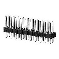
Conn Unshrouded Header HDR 26 POS 2.54mm Solder ST Thru-Hole
Manufacturer
TE Connectivity
Type
Unshrouded Headerr
Datasheet
1.1-102618-8.pdf
(320 pages)
Specifications of 6-146256-3
Pitch
2.54 mm
Number Of Rows
2
Number Of Contacts
26
Gender
HDR
Contact Plating
Gold Over Nickel
Termination Method
Solder
Product Type
Connector
Mount Angle
Vertical
Pcb Mount Retention
Without
Surface Mount Compatible
Yes
Board Standoff
With
Mounting Ears
Without
Mating Connector Lock
Without
Post Size (mm [in])
0.64 [.025]
Mating Post Length (mm [in])
5.84 [0.230]
Panel Mount Retention
Without
Insulation Resistance (m?)
5,000
Dielectric Withstanding Voltage (v)
750
Termination Post Length (mm [in])
3.05 [0.120]
Solder Tail Contact Plating
Tin over Nickel, Matte Tin over Nickel
Header Type
Breakaway
Number Of Positions
26
Centerline (mm [in])
2.54 [0.100]
Row-to-row Spacing (mm [in])
2.54 [0.100]
Selectively Loaded
No
Mount Type
Printed Circuit Board
Contact Plating, Mating Area, Material
Gold (15)
Contact Shape
Square
Contact Base Material
Phosphor Bronze
Housing Material
Thermoplastic - GF
Ul Flammability Rating
UL 94V-0
Rohs/elv Compliance
RoHS compliant, ELV compliant
Lead Free Solder Processes
Wave solder capable to 240°C, Wave solder capable to 260°C, Wave solder capable to 265°C, Reflow solder capable to 245°C, Reflow solder capable to 260°C, Pin-in-Paste capable to 245°C, Pin-in-Paste capable to 260°C
Rohs/elv Compliance History
Always was RoHS compliant
Operating Temperature (°c)
-65 – +105
High Temperature Housing
Yes
High Speed Serial Data Connector
No


5
204
Material
Black polyester
Technical Documents
The barrier insert can be
used on double row headers
(.100 x .100 [2.54 x 2.54]
centers), including shrouded
versions—3 and 4 sides,
as well as unshrouded
straight post headers. With
one barrier insert several
configurations can be
obtained, providing headers
with capabilities of accept-
ing various combinations of
polarized and non-polarized
AMPMODU connectors.
For unshrouded headers,
the barrier insert is used
to establish polarization
and to compartmentalize
the header. For shrouded
headers, the barrier insert is
used to compartmentalize
the header, while maintaining
polarization. The barrier
insert itself is notched to
facilitate cutting off the
ends with a simple tool
such as tin snips or scissors
to achieve the desired
configuration.
Catalog 1307819
Revised 8-08
www.tycoelectronics.com
— page 276
are metric equivalents.
Dimensions are in inches and
millimeters unless otherwise
specified. Values in brackets
AMPMODU Interconnection System
Accessories: Barrier Insert, Part No. 87743-1
Barrier Insert Cutoffs
Typical Barrier Insert Applications
For Unshrouded Double-Row, Straight Post Headers,
.100 x .100 [2.54 x 2.54] Centers
Note: All configurations of barrier inserts compartmentalize headers and maintain polarization,
For Shrouded Double-Row, 3 and 4 Sided Headers,
.100 x .100 [2.54 x 2.54] Centers
Note: Right-angle (Figs. 2 and 3) and “T” (Fig. 1) configurations of barrier insert establish
Note: All part numbers are RoHS compliant.
[7.98]
.314
(Left and Right Sides)
[0.94]
.037
Partial Cutoff
except bar (Fig. 4) configuration, which is used primarily for compartmentalizing headers.
polarization; bar (Fig. 4) configuration of barrier insert compartmentalizes header.
Fig. 1
See Fig. 2
See Fig. 3
[11.33]
Dimensions are shown for
reference purposes only.
Specifications subject
to change.
.446
[3.23]
.127
Complete Cutoff
Partial Cutoff
(Right Side)
(Left Side)
Fig. 2
See Fig. 4
See Fig. 4
USA: 1-800-522-6752
Canada: 1-905-470-4425
Mexico: 01-800-733-8926
C. America: 52-55-1106-0803
[8.64]
.340
45°
See Fig. 1
See Fig. 1
Complete Cutoff
Partial Cutoff
(Right Side)
(Left Side)
[0.76]
.030
Fig. 3
[2.29]
.090
[2.54]
South America: 55-11-2103-6000
Hong Kong: 852-2735-1628
Japan: 81-44-844-8013
UK: 44-8706-080-208
.100
[2.21]
[1.19]
.087
.047
(Left and Right Sides)
See Fig. 2
Complete Cutoff
See Fig. 3
Fig. 4
Thru Typ. (2)
[0.74±0.03]
Dia. x
[0.79-1.09]
remainder
.029±.001
.031-.043
[0.76]
Deep—
.030
Dia.
[2.39]
.094
[6.35]
.250[
Related parts for 6-146256-3
Image
Part Number
Description
Manufacturer
Datasheet
Request
R


Part Number:
Description:
Barrier Terminal Blocks TRI-BARRIER .375 14
Manufacturer:
Tyco Electronics

Part Number:
Description:
CONN BARRIER STRIP 14POS .375
Manufacturer:
Tyco Electronics
Datasheet:

Part Number:
Description:
BARRIER BLOCK 6POS .438"
Manufacturer:
Cinch Connectors
Datasheet:

Part Number:
Description:
CONN TERM BLOCK 3POS 14-6AWG
Manufacturer:
Tyco Electronics
Datasheet:

Part Number:
Description:
6-1415035-1
Manufacturer:
TE Connectivity
Datasheet:

Part Number:
Description:
Manufacturer:
TE Connectivity
Datasheet:

Part Number:
Description:
Res Thick Film 2512 6.8 Ohm 5% 1W ±350ppm/°C Molded SMD T/R
Manufacturer:
TE Connectivity
Datasheet:

Part Number:
Description:
PLUG, SOLARLOK, 6MM, NEG
Manufacturer:
TE Connectivity
Datasheet:

Part Number:
Description:
SKT,SODIMM,144P,SDRAM3.3V,STD,T&R
Manufacturer:
TE Connectivity
Datasheet:

Part Number:
Description:
Manufacturer:
TE Connectivity
Datasheet:

Part Number:
Description:
Conn Shielded Circular Subminiature SKT 3 POS Solder ST Thru-Hole 3 Terminal 1 Port
Manufacturer:
TE Connectivity
Datasheet:

Part Number:
Description:
FASTIN-FASTON RECEP 6,35
Manufacturer:
TE Connectivity
Datasheet:

Part Number:
Description:
TERMINAL, SOCKET, FASTON, 18-15AWG
Manufacturer:
TE Connectivity
Datasheet:

Part Number:
Description:
Manufacturer:
TE Connectivity
Datasheet: