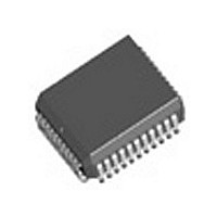
DG884AM883E3 Vishay, DG884AM883E3 Datasheet - Page 12

DG884AM883E3
Manufacturer Part Number
DG884AM883E3
Description
Manufacturer
Vishay
Datasheet
1.DG884AM883E3.pdf
(23 pages)
Specifications of DG884AM883E3
Array Configuration
8x4
Number Of Arrays
1
Screening Level
Industrial
Pin Count
44
Package Type
PLCC
Power Supply Requirement
Triple
Lead Free Status / RoHS Status
Compliant
DG884
Vishay Siliconix
APPLICATIONS
Power Supplies and Decoupling
A useful feature of the DG884 is its power supply flexibility. It
can be operated from dual supplies, or a single positive
supply (V- connected to 0 V) if required. Allowable operating
voltage ranges are shown in Operating Voltage Range
(Typical Characteristics) graph, page 6.
Note that the analog signal must not go below V- by more
than 0.3 V (see absolute maximum ratings). However, the
addition of a V- pin has a number of advantages:
1)
2)
3)
It is established RF design practice to incorporate sufficient
bypass capacitors in the circuit to decouple the power
supplies to all active devices in the circuit. The dynamic
performance of the DG884 is adversely affected by poor
decoupling of power supply pins. Also, since the substrate of
the device is connected to the negative supply, proper
decoupling of this pin is essential.
www.vishay.com
12
It allows flexibility in analog signal handling, i.e. with
V- = - 5 V and V+ = 15 V, up to ± 5 V ac signals can
be accepted.
The value of on-capacitance [C
by increasing the value of V-. It is useful to note that
optimum video differential phase and gain occur
when V- is - 3 V. Note that V+ has no effect on C
V- eliminates the need to bias an ac analog signal
using potential dividers and large decoupling
capacitors.
C
2
51
Figure 14. DG884 Power Supply Decoupling
Ω
C
+
+ 5 V
1
V
DG884
L
V
C
+
51
1
3 V
+ 15 V
V+
Ω
C
+
1
51
Ω
C
2
C
C
C
2
1
2
= 1 µ F T antalum
= 100 nF Ceramic
S(on)
] may be reduced
S(on)
.
Rules:
1)
2)
3)
Recommended decoupling capacitors are 1
tantalum bead, in parallel with 100 nF monolithic ceramic.
4)
The V
device is primarily designed to be TTL or CMOS logic
compatible with + 5 V applied to V
threshold can be raised simply by increasing V
L
Decoupling capacitors should be incorporated on all
power supply pins (V+, V-, V
They should be mounted as close as possible to the
device pins.
Capacitors should have good high frequency
characteristics - tantalum bead and/or monolithic
ceramic disc types are suitable.
Additional high frequency protection may be provided
by 51 Ω carbon film resistors connected in series with
the power supply pins (see Figure 14).
pin permits interface to various logic types. The
6
5
4
3
2
1
0
0
Figure 15. Switching Threshold Voltage vs. V
2
4
V
6
L
– Logic Supply (V)
8
S-71241–Rev. H, 25-Jun-07
L
10
Document Number: 70071
).
L
. The actual logic
12
14
L
.
to 10 µF
16
18
L


