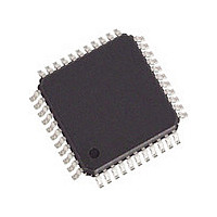
DJLXT360LE.A2 Cortina Systems Inc, DJLXT360LE.A2 Datasheet - Page 3

DJLXT360LE.A2
Manufacturer Part Number
DJLXT360LE.A2
Description
Manufacturer
Cortina Systems Inc
Datasheet
1.DJLXT360LE.A2.pdf
(56 pages)
Specifications of DJLXT360LE.A2
Number Of Transceivers
1
Operating Supply Voltage (typ)
5V
Screening Level
Industrial
Mounting
Surface Mount
Operating Supply Voltage (min)
4.75V
Operating Supply Voltage (max)
5.25V
Operating Temperature (min)
-40C
Operating Temperature (max)
85C
Lead Free Status / RoHS Status
Supplier Unconfirmed
Available stocks
Company
Part Number
Manufacturer
Quantity
Price
LXT360 Transceiver
Datasheet: Long Form
249231, Revision 2.1
24 January 2008
Contents
1.0
2.0
3.0
4.0
Cortina Systems
Pin Assignments and Signal Descriptions ................................................................................. 8
1.1
Functional Description................................................................................................................ 14
2.1
2.2
2.3
2.4
2.5
2.6
2.7
Register Definitions..................................................................................................................... 30
Application Information .............................................................................................................. 36
Mode Dependent Signals ..................................................................................................... 8
Initialization ......................................................................................................................... 14
2.1.1
Transmitter.......................................................................................................................... 14
2.2.1
2.2.2
2.2.3
2.2.4
2.2.5
Receiver.............................................................................................................................. 16
2.3.1
2.3.2
2.3.3
2.3.4
Jitter Attenuation................................................................................................................. 17
Hardware Mode .................................................................................................................. 17
Host Mode .......................................................................................................................... 17
2.6.1
Diagnostic Mode Operation ................................................................................................ 20
2.7.1
2.7.2
2.7.3
2.7.4
2.7.5
®
LXT360 Integrated T1/E1 LH/SH Transceiver for DS1/DSX-1 or PRI Applications
Reset Operation..................................................................................................... 14
Transmit Digital Data Interface .............................................................................. 14
Transmit Monitoring ............................................................................................... 15
Transmit Drivers .................................................................................................... 15
Transmit Idle Mode ................................................................................................ 15
Transmit Pulse Shape ........................................................................................... 15
Receive Equalizer.................................................................................................. 16
Receive Data Recovery ......................................................................................... 16
Receive Digital Data Interface ............................................................................... 16
Receiver Monitor Mode.......................................................................................... 16
Interrupt Handling .................................................................................................. 18
Loopback Modes ................................................................................................... 21
2.7.1.1
2.7.1.2
2.7.1.3
2.7.1.4
2.7.1.5
Internal Pattern Generation and Detection ............................................................ 25
2.7.2.1
2.7.2.2
2.7.2.3
Error Insertion and Detection................................................................................. 27
2.7.3.1
2.7.3.2
2.7.3.3
2.7.3.4
2.7.3.5
2.7.3.6
Alarm Condition Monitoring ................................................................................... 28
2.7.4.1
2.7.4.2
2.7.4.3
2.7.4.4
Other Diagnostic Reports ...................................................................................... 29
2.7.5.1
2.7.5.2
Local Loopback (LLOOP) ...................................................................... 21
Analog Loopback (ALOOP) ................................................................... 22
Remote Loopback (RLOOP).................................................................. 23
Network Loopback (NLOOP) ................................................................. 23
Dual Loopback (DLOOP) ....................................................................... 24
Transmit All Ones (TAOS) ..................................................................... 25
Quasi-Random Signal Source (QRSS).................................................. 25
In-Band Network Loop Up or Down Code Generator ............................ 27
Bipolar Violation Insertion (INSBPV)...................................................... 27
Logic Error Insertion (INSLER) .............................................................. 27
Logic Error Detection (QPD) .................................................................. 27
Bipolar Violation Detection (BPV) .......................................................... 28
HDB3 Code Violation Detection (CODEV)............................................. 28
HDB3 Zero Substitution Violation Detection (ZEROV) .......................... 28
Loss of Signal (LOS).............................................................................. 28
Alarm Indication Signal Detection (AIS)................................................. 29
Driver Failure Monitor Open (DFMO)..................................................... 29
Elastic Store Overflow/Underflow (ESOVR and ESUNF) ...................... 29
Receive Line Attenuation Indication....................................................... 29
Built-In Self Test (BIST) ......................................................................... 29
TM
TM
Contents
Page 3


