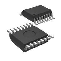
MIC2583-MBQS Micrel Inc, MIC2583-MBQS Datasheet - Page 21

MIC2583-MBQS
Manufacturer Part Number
MIC2583-MBQS
Description
IC,Power Control/Management,CMOS,SSOP,16PIN,PLASTIC
Manufacturer
Micrel Inc
Type
Hot-Swap Controllerr
Datasheet
1.MIC2582-JYM.pdf
(25 pages)
Specifications of MIC2583-MBQS
Applications
General Purpose
Internal Switch(s)
No
Voltage - Supply
2.3 V ~ 13.2 V
Operating Temperature
-40°C ~ 85°C
Mounting Type
Surface Mount
Package / Case
16-SSOP (0.150", 3.90mm Width)
Linear Misc Type
Positive Low Voltage
Family Name
MIC2583
Package Type
QSOP
Operating Supply Voltage (min)
2.3V
Operating Supply Voltage (max)
13.2V
Operating Temperature (min)
-40C
Operating Temperature (max)
85C
Operating Temperature Classification
Industrial
Product Depth (mm)
3.99mm
Product Height (mm)
1.4mm
Product Length (mm)
4.98mm
Mounting
Surface Mount
Pin Count
16
Lead Free Status / RoHS Status
Contains lead / RoHS non-compliant
Lead Free Status / RoHS Status
Contains lead / RoHS non-compliant
Thus:
Assume T
the drain leads, no airflow.
Recalling from our previous approximation hint, the part
has an R
Assume it has been carrying just about 2.5A for some
time.
When performing this calculation, be sure to use the
highest anticipated ambient temperature (T
which the MOSFET will be operating as the starting
temperature, and find the operating junction temperature
increase (∆T
final junction temperature is found by adding T
∆T
close approximation may take one or two iterations, and
the calculation tends to converge quickly.
Then the starting (steady-state) T
Micrel, Inc.
April 2009
J
. Since this is not a closed-form equation, getting a
T
T
J
J
≅ T
≅ T
≅ 55ºC + [17mΩ + (55ºC-25ºC)(0.005)(17mΩ)]
ON
A(MAX)
A(MAX)
A
= 55°C maximum, 1 square inch of copper at
of (0.0335/2) = 17mΩ at 25°C.
J
) from that point. Then, as shown next, the
+ [R
+ ∆T
x I
2
ON
x R
J
+ T
θ(JA)
A(MAX)
– T
J
A
is:
)(0.005/ºC)(R
Figure 10. Transient Thermal Impedance
A(MAX)
A(MAX)
ON
)]
) in
and
21
Iterate the calculation once to see if this value is within a
few percent of the expected final value. For this iteration
we will start with T
of 61.1°C:
So our original approximation of 61.1ºC was very close
to the correct value. We will use T
Finally, add the temperature increase due to the
maximum power dissipation calculated from a “single
event”, (11.25W)(50ºC/W)(0.08) = 45ºC to the steady-
state T
acceptable maximum junction temperature for this part.
T
T
T
J
J
J
≅ (55ºC + (0.122W)(50ºC/W)
≅ T
≅ (55ºC + (0.125W)(50ºC/W) ≅ 61.27ºC
≅ 61.1ºC
J
to get T
A
+ [17mΩ + (61.1ºC-25ºC)(0.005)(17mΩ)]
x (2.5A)
x (2.5A)
J
J(TRANSIENT MAX.)
equal to the already calculated value
2
x (50ºC/W)
2
x (50ºC/W)
J
= 106ºC. This is an
= 61ºC.
MIC2582/MIC2583
M9999-043009-C


