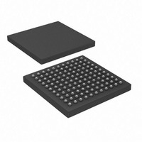
PIC32MX320F128LT-80I/BG Microchip Technology, PIC32MX320F128LT-80I/BG Datasheet - Page 131

PIC32MX320F128LT-80I/BG
Manufacturer Part Number
PIC32MX320F128LT-80I/BG
Description
128 KB Flash, 32 KB RAM, 80 MHz, 10-Bit ADC 121 XBGA 10x10x1.20mm T/R
Manufacturer
Microchip Technology
Series
PIC® 32MXr
Datasheets
1.MA320002.pdf
(208 pages)
2.DM320001.pdf
(44 pages)
3.PIC32MX320F032H-40IPT.pdf
(48 pages)
4.PIC32MX320F032H-40IPT.pdf
(66 pages)
5.PIC32MX320F032H-40IPT.pdf
(22 pages)
Specifications of PIC32MX320F128LT-80I/BG
Core Processor
MIPS32® M4K™
Core Size
32-Bit
Speed
80MHz
Connectivity
I²C, IrDA, LIN, PMP, SPI, UART/USART
Peripherals
Brown-out Detect/Reset, POR, PWM, WDT
Program Memory Size
128KB (128K x 8)
Program Memory Type
FLASH
Ram Size
16K x 8
Voltage - Supply (vcc/vdd)
2.3 V ~ 3.6 V
Data Converters
A/D 16x10b
Oscillator Type
Internal
Operating Temperature
-40°C ~ 85°C
Package / Case
121-TFBGA
Processor Series
PIC32MX3xx
Core
MIPS
3rd Party Development Tools
52713-733, 52714-737
Development Tools By Supplier
PG164130, DV164035, DV244005, DV164005, DM320001, DM320002, MA320001
Lead Free Status / RoHS Status
Lead free / RoHS Compliant
Number Of I /o
-
Eeprom Size
-
Lead Free Status / Rohs Status
Details
Available stocks
Company
Part Number
Manufacturer
Quantity
Price
Company:
Part Number:
PIC32MX320F128LT-80I/BG
Manufacturer:
Microchip Technology
Quantity:
10 000
- MA320002 PDF datasheet
- DM320001 PDF datasheet #2
- PIC32MX320F032H-40IPT PDF datasheet #3
- PIC32MX320F032H-40IPT PDF datasheet #4
- PIC32MX320F032H-40IPT PDF datasheet #5
- Current page: 131 of 208
- Download datasheet (5Mb)
26.0
REGISTER 26-1:
© 2010 Microchip Technology Inc.
bit 31
bit 23
bit 15
bit 7
Legend:
R = Readable bit
U = Unimplemented bit
bit 31
bit 30-29
bit 28
bit 27-25
bit 24
bit 23-20
Note:
R/P
r-0
r-1
r-1
—
—
—
SPECIAL FEATURES
reference source. To complement the infor-
This data sheet summarizes the features of
the PIC32MX3XX/4XX family of devices. It
is not intended to be a comprehensive
mation in this data sheet, refer to the related
section in the “PIC32MX Family Reference
Manual” (DS61132), which is available from
the
(www.microchip.com/PIC32).
Reserved: Write ‘0’
Reserved: Write ‘1’
CP: Code-Protect bit
Prevents boot and program Flash memory from being read or modified by an external
programming device.
1 = Protection disabled
0 = Protection enabled
Reserved: Write ‘1’
BWP: Boot Flash Write-Protect bit
Prevents boot Flash memory from being modified during code execution.
1 = Boot Flash is writable
0 = Boot Flash is not writable
Reserved: Write ‘1’
R/P
r-1
r-1
r-1
Microchip
—
—
—
DEVCFG0: DEVICE CONFIGURATION WORD 0
PWP<3:0>
W = Writable bit
-n = Bit Value at POR: (‘0’, ‘1’, x = Unknown)
R/P
r-1
r-1
r-1
—
—
—
web
site
R/P
R/P
CP
r-1
r-1
—
—
P = Programmable bit
ICESEL
PIC32MX3XX/4XX devices include several features
intended to maximize application flexibility and reliabil-
ity and minimize cost through elimination of external
components. These are:
• Flexible Device Configuration
• Watchdog Timer
• JTAG Interface
• In-Circuit Serial Programming™ (ICSP™)
26.1
The Configuration bits can be programmed to select
various device configurations.
R/P
R/P
r-1
r-1
—
—
PIC32MX3XX/4XX
Configuration Bits
R/P
r-1
r-1
r-1
—
—
—
PWP<7:4>
r = Reserved bit
R/P
R/P
r-1
r-1
—
—
DEBUG<1:0>
DS61143G-page 131
BWP
R/P
R/P
R/P
r-1
—
bit 24
bit 16
bit 8
bit 0
Related parts for PIC32MX320F128LT-80I/BG
Image
Part Number
Description
Manufacturer
Datasheet
Request
R

Part Number:
Description:
Manufacturer:
Microchip Technology Inc.
Datasheet:

Part Number:
Description:
Manufacturer:
Microchip Technology Inc.
Datasheet:

Part Number:
Description:
Manufacturer:
Microchip Technology Inc.
Datasheet:

Part Number:
Description:
Manufacturer:
Microchip Technology Inc.
Datasheet:

Part Number:
Description:
Manufacturer:
Microchip Technology Inc.
Datasheet:

Part Number:
Description:
Manufacturer:
Microchip Technology Inc.
Datasheet:

Part Number:
Description:
Manufacturer:
Microchip Technology Inc.
Datasheet:

Part Number:
Description:
Manufacturer:
Microchip Technology Inc.
Datasheet:


