PIC32MX320F128LT-80I/BG Microchip Technology, PIC32MX320F128LT-80I/BG Datasheet - Page 34
PIC32MX320F128LT-80I/BG
Manufacturer Part Number
PIC32MX320F128LT-80I/BG
Description
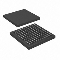
128 KB Flash, 32 KB RAM, 80 MHz, 10-Bit ADC 121 XBGA 10x10x1.20mm T/R
Manufacturer
Microchip Technology
Series
PIC® 32MXr
Datasheets
1.MA320002.pdf
(208 pages)
2.DM320001.pdf
(44 pages)
3.PIC32MX320F032H-40IPT.pdf
(48 pages)
4.PIC32MX320F032H-40IPT.pdf
(66 pages)
5.PIC32MX320F032H-40IPT.pdf
(22 pages)
Specifications of PIC32MX320F128LT-80I/BG
Core Processor
MIPS32® M4K™
Core Size
32-Bit
Speed
80MHz
Connectivity
I²C, IrDA, LIN, PMP, SPI, UART/USART
Peripherals
Brown-out Detect/Reset, POR, PWM, WDT
Program Memory Size
128KB (128K x 8)
Program Memory Type
FLASH
Ram Size
16K x 8
Voltage - Supply (vcc/vdd)
2.3 V ~ 3.6 V
Data Converters
A/D 16x10b
Oscillator Type
Internal
Operating Temperature
-40°C ~ 85°C
Package / Case
121-TFBGA
Processor Series
PIC32MX3xx
Core
MIPS
3rd Party Development Tools
52713-733, 52714-737
Development Tools By Supplier
PG164130, DV164035, DV244005, DV164005, DM320001, DM320002, MA320001
Lead Free Status / RoHS Status
Lead free / RoHS Compliant
Number Of I /o
-
Eeprom Size
-
Lead Free Status / Rohs Status
Details
Available stocks
Company
Part Number
Manufacturer
Quantity
Price
Company:

Part Number:
PIC32MX320F128LT-80I/BG
Manufacturer:
Microchip Technology
Quantity:
10 000


PIC32MX3XX/4XX
2.9
If MPLAB ICD 2, ICD 3 or REAL ICE is selected as a
debugger, it automatically initializes all of the A/D input
pins (ANx) as “digital” pins by setting all bits in the
ADPCFG register.
The bits in this register that correspond to the A/D pins
that are initialized by MPLAB ICD 2, ICD 3 or REAL
ICE, must not be cleared by the user application
firmware; otherwise, communication errors will result
between the debugger and the device.
If your application needs to use certain A/D pins as
analog input pins during the debug session, the user
application must clear the corresponding bits in the
ADPCFG register during initialization of the ADC
module.
When MPLAB ICD 2, ICD 3 or REAL ICE is used as a
programmer, the user application firmware must
correctly configure the ADPCFG register. Automatic
initialization of this register is only done during
debugger operation. Failure to correctly configure the
register(s) will result in all A/D pins being recognized as
analog input pins, resulting in the port value being read
as a logic ‘0’, which may affect user application
functionality.
DS61143G-page 34
Configuration of Analog and
Digital Pins During ICSP
Operations
2.10
Unused I/O pins should not be allowed to float as
inputs. They can be configured as outputs and driven
to a logic-low state.
Alternately, inputs can be reserved by connecting the
pin to V
the pin as an input.
SS
Unused I/Os
through a 1k to 10k resistor and configuring
© 2010 Microchip Technology Inc.
Related parts for PIC32MX320F128LT-80I/BG
Image
Part Number
Description
Manufacturer
Datasheet
Request
R

Part Number:
Description:
Manufacturer:
Microchip Technology Inc.
Datasheet:
Part Number:
Description:
Manufacturer:
Microchip Technology Inc.
Datasheet:
Part Number:
Description:
Manufacturer:
Microchip Technology Inc.
Datasheet:
Part Number:
Description:
Manufacturer:
Microchip Technology Inc.
Datasheet:
Part Number:
Description:
Manufacturer:
Microchip Technology Inc.
Datasheet:
Part Number:
Description:
Manufacturer:
Microchip Technology Inc.
Datasheet:
Part Number:
Description:
Manufacturer:
Microchip Technology Inc.
Datasheet:
Part Number:
Description:
Manufacturer:
Microchip Technology Inc.
Datasheet: