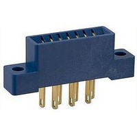
NRT-C Omron, NRT-C Datasheet - Page 3

NRT-C
Manufacturer Part Number
NRT-C
Description
SWITCH
Manufacturer
Omron
Datasheet
1.NRT-C.pdf
(10 pages)
Specifications of NRT-C
Leaded Process Compatible
Yes
Peak Reflow Compatible (260 C)
Yes
Lead Free Status / RoHS Status
Lead free / RoHS Compliant
For Use With
M7E Series Digital Displays
Lead Free Status / Rohs Status
Lead free / RoHS Compliant
Other names
NRTC
Q3652747
Q3652747
Available stocks
Company
Part Number
Manufacturer
Quantity
Price
Part Number:
NRT-CP
Manufacturer:
OMRON/欧姆龙
Quantity:
20 000
Installation
■ Input Codes
Operation Examples of RBI and RBO
Zero suppression functions and RBO is low when the display is 0, the decimal point
is not lit, and RBI is low.
Example 1: Zero blanking is not required and the RBI input and RBO output of each
Example 2: Wired as shown when there is zero blanking. If the data of the rightmost
Example 3: Zero blanking is valid for only the digits on the left of the lit digit and
Example 4: Zero blanking is valid for the second digit and the following digits that are
Note: Use RBO output for the connection with RBI input only.
■ Terminal Arrangement/Functions
Terminal Arrangement
Decimal Display Unit
Terminal Functions
V
RBO
RBI
A
B
C
D
DP
LE
R/G
G
Terminal
symbol
digit are open.
digit is 0, 0 will be displayed.
decimal point.
on the right of the lit digit and decimal point. If the first- to fourth-digit
values are all 0 and the decimal point is lit with the fourth digit, 0. 0@@
will be displayed. (There is no data in @@.)
Power supply Positive (+) power-supply terminal.
Control
output
Control input Turns OFF when the input is low while the decimal point is not lit and the
Data inputs
Data input
Control input Latch input: The immediately preceding display condition is retained.
Control input Set low for green display and high for red display. (See note.)
Power supply 0-V power-supply (ground) input terminal (GND).
Name
http://www.ia.omron.com/
Low is output during zero blanking.
contents of display is 0.
The decimal point lights. Operates independently from the LE terminal.
A (2
B (2
C (2
D (2
Note: The R/G terminal is only for two-color models. It is
0
1
2
3
)
)
)
)
NC on the single-color models.
Displays a digit or symbol corresponding to the value of the
Decimal display uses 0 to 9; nothing will be displayed for
binary code signal.
higher values.
NRT-@ Connector pin No.
Note: Values in parentheses apply to the
Power supply input (+)
NRT-@ Connector's pin numbers.
Data input
Decimal point input
Control input (latch input)
Control input (color selection input) (See note.)
Power supply input 0 V
Zero suppress output
Zero suppress input
Function
Power
supply 0 V
Power
supply (+)
Unit Display Unit
(c)Copyright OMRON Corporation 2007 All Rights Reserved.
Example 1
Example 2
Example 3
Example 4
Fourth digit
Power
supply
input
Signal
inputs
Note: Only for the M7E-02DRGN2.
Signal Input Circuit
Negative Logic Standard
Model
■ Block Diagram
Note: Circled numbers are the
Signal input
Third digit
0 V
GND
connector pin numbers.
+5 V
1.8 kΩ
Switching
regulator
Input
circuit/
driver
circuit
Second digit
20 kΩ
Custom IC
Zero blanking
circuit
LED display
elements
First digit
M7E
3


