1934357-1 TE Connectivity, 1934357-1 Datasheet
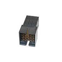
RA HEADER 3 PAIR / 10 COLUMN

1934357-1

Manufacturer Part Number
1934357-1
Description
RA HEADER 3 PAIR / 10 COLUMN
Manufacturer
TE Connectivity
Datasheet

Specifications of 1934357-1

Connector Type
Header
Pcb Mounting Orientation
Right Angle
Pcb Mount Retention
With
Termination Method To Pc Board
Through Hole - Press Fit
Pcb Mount Alignment
Without
Sealed
No
Ul File Number
E28476
Stackable
No
Module Type
Center
Data Rate (gb/s)
10.000
Differential Impedance (?)
100
Contact - Rated Current (a)
0.5
Hot Pluggable
No
Operating Voltage Reference
AC
Operating Voltage (vac)
250
Tail Length (mm [in])
2.2 [0.087]
Header Type
Partially Shrouded
Number Of Positions
90
Number Of Signal Positions
60
Number Of Rows
9
Number Of Columns
10
Pcb Mount Retention Type
Compliant Posts
Centerline (mm [in])
1.91 [0.075]
Row-to-row Spacing (mm [in])
1.40 [0.055]
Mating Retention
Without
Contact Type
Pin
Contact Design
Rectangular Post
Contact Base Material
Phosphor Bronze
Contact Plating, Mating Area, Material
Gold
Contact Plating, Mating Area, Thickness (µm [?in])
0.76 [29.92]
Tail Plating Material
Matte Tin
Tail Plating, Thickness (µm [?in])
0.5 [20]
Connector Style
Plug
End Wall Location
Open
Housing Color
Black
Mating Alignment
With
Mating Alignment Type
Guide Slot
Housing Material
Liquid Crystal Polymer (LCP)
Ul Flammability Rating
UL 94V-0
Number Of Pairs Per Connector
30
Pairs Per Column
3
Differential Signaling
With
Rohs/elv Compliance
RoHS compliant, ELV compliant
Lead Free Solder Processes
Not relevant for lead free process
Rohs/elv Compliance History
Always was RoHS compliant
Agency/standard
UL
Ul Rating
Recognized
Ul Voltage Rating (vac)
250
Operating Temperature (°c [°f])
-65 – +90 [-85 – +194]
Board-to-board Configuration
Co-Planar
Pcb Thickness, Recommended (mm [in])
1.57 [0.062]
Contact Transmits (typical Application)
Signal (Data)
Packaging Method
Tube
|
|
|
|
1.
1.1.
1.2.
1.3.
2.
2.1.
2.2.
2.3.
3.
3.1.
3.2.
©2011 Tyco Electronics Corporation, a TE Connectivity Ltd. Com pany
All Rights Reserved
| Indicates Change
* Tradem ark TE Connectivity, TE connectivity (logo), and TE (logo) are tradem arks. Other logos, product and/or Com pany nam es m ay be tradem arks of their respective owners.
SCOPE
Content
This specification covers perform ance, tests and quality requirem ents for the Z-PACK TinMan*
Connector System that uses a m odular concept to interconnect two printed circuit boards. Both
receptacle and pin connectors are connected to the printed circuit board with plated thru-hole com pliant
press-fit leads.
Qualification
W hen tests are perform ed on the subject product line, procedures specified in Figure 1 shall be used.
All inspections shall be perform ed using the applicable inspection plan and product drawing.
Qualification Test Results
Successful qualification testing on the subject product line was com pleted on 16Apr08, additional
testing was com pleted on 29Mar11. The Qualification Test Report num ber for this testing is 501-678.
APPLICABLE DOCUM ENTS
The following docum ents form a part of this specification to the extent specified herein. Unless
otherwise specified, the latest edition of the docum ent applies. In the event of conflict between the
requirem ents of this specification and the product drawing, the product drawing shall take precedence.
In the event of conflict between the requirem ents of this specification and the referenced docum ents,
this specification shall take precedence.
TE Connectivity (TE) Docum ents
!
!
Industry Standard
EIA-364: Electrical Connector/Socket Test Procedures Including Environm ental Classifications
Reference Docum ent
109-197: Test Specification (TE Test Specifications vs EIA and IEC Test Methods)
REQUIREM ENTS
Design and Construction
Product shall be of the design, construction and physical dim ensions specified on the applicable product
drawing.
Materials
Materials used in the construction of this product shall be as specified on the applicable product
drawing.
114-13202: Application Specification (Z-PACK TinMan* Connector System )
501-678: Qualification Test Report (Z-PACK TinMan* Connector System )
Product
Specification
Z-PACK TinMan* Connector System
For latest revision, visit our website at www.te.com /docum ents.
For Regional Custom er Service, visit our website at www.te.com
108-2303
20Jul11 Rev B
1 of 8
LOC B

Related parts for 1934357-1

1934357-1 Summary of contents

Page 1

... All Rights Reserved | Indicates Change * Tradem ark TE Connectivity, TE connectivity (logo), and TE (logo) are tradem arks. Other logos, product and/or Com pany nam tradem arks of their respective owners. For latest revision, visit our website at www.te.com /docum ents. For Regional Custom er Service, visit our website at www.te.com ...

Page 2

Ratings ! Voltage: 250 volts AC m axim um peak ( inim um breakdown voltage) ! Current: 0.5 ampere per signal contact (fully loaded) ! Tem perature: -65 to 90°C 3.4. Perform ance and Test Description Product ...

Page 3

Test Description Vibration, random . Mechanical shock. Durability. Mating force. Unm ating force. Com pliant pin insertion force. Com pliant pin retention force. Minute disturbance. Therm al shock. Rev B Requirem ent MECHANICAL No discontinuities icrosecond or ...

Page 4

Test Description Hum idity/tem perature cycling. Tem perature life. Mixed flowing gas. Dust contam ination. Shall meet visual requirements, show no physical damage, and meet requirements of additional NOTE tests as specified in the Product Qualification and Requalification Test Sequence ...

Page 5

Product Qualification and Requalification Test Sequence . Test or Examination Initial examination of product Low level contact resistance Low level compliant pin resistance Insulation resistance Withstanding voltage Temperature rise vs current Vibration Mechanical shock Durability Mating force Unmating force ...

Page 6

QUALITY ASSURANCE PROVISIONS 4.1. Qualification Testing A. Specim en Selection Specim ens shall be prepared in accordance with applicable Instruction Sheets and shall be selected at random from current production. Each test group shall consist inim ...

Page 7

Low Level Contact Resistance Measurem ent Points Rev B Figure 3 108-2303 ...

Page 8

Vibration & Mechanical Shock Mounting Fixture Rev B Figure 4 108-2303 ...

Related keywords